


33
Installation
Signal and Optional Switch Connections
All signal and switch connections are made at TB501.
Terminal block orientation and terminal names are identical
for all VFD01, -02 and -04 series drives. Use 20 - 24 AWG
wire for speed adjust potentiometer and switch connections.
ENABLE/DISABLE switch
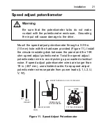
Connect a single-pole, single-throw ENABLE/DISABLE
switch between the ENABLE (E2) and COMMON (E1)
terminals as shown. Open the switch to disable the drive
and coast to a stop. Close the switch to accelerate to set
speed at a rate controlled by the ACCEL trimpot.
E2
E1 (COMMON)
S1
S2
D
S3
ENABLE/DISABLE SWITCH
OPEN TO DISABLE
TB501
Figure 20. Enable / Disable Switch connections to TB501