Forward Speed (FWD SPEED):
The FWD SPEED se�ng determines the actuator speed in the forward
direc�on (when A1 is posi�ve with respect to A2). Turning the trim pot clockwise increases forward
motor speed.
Reverse Speed (REV SPEED):
The REV SPEED se�ng determines the actuator speed in the reverse
direc�on (when A2 is posi�ve with respect to A1). Turning the trim pot clockwise increases reverse
motor speed.
Motor Torque (MOTOR CL):
The MOTOR CL sets the maximum amount of current the actuator can
draw when accelera�ng (motoring) the actuator in either direc�on. To calibrate the MOTOR CL:
1. With the power disconnected from the drive, connect a DC ammeter in series with the
1.
actuator.
2. Set the MOTOR CL trim pot to minimum (full CCW).
3. Command minimum posi�on (posi�on poten�ometer full CCW or analog signal at 0 VDC).
4. Carefully lock the actuator. Be sure that it is is firmly mounted.
5. Apply power source and command the actuator to move. The actuator should be stopped.
6. Slowly adjust the MOTOR CL trim pot CW un�l the actuator current is 150% of rated current.
7. Command minimum posi�on (posi�on poten�ometer full CCW or analog signal at 0 VDC).
8. Remove power source.
9. Remove the stall from the actuator.
10. Remove the ammeter in series with the actuator if it is no longer needed.
Regen Torque (REGEN CL):
The REGEN CL sets the maximum amount of current the actuator can draw
when stopping in either direc�on. If the red LED comes on when stopping, turn this trim pot clockwise
to increase the current limit.
Posi�onal Error (DEADBAND):
The DEADBAND trim pot sets the allowed error around the desired final
posi�on. Turning the trim pot clockwise allows for more error. If the DEADBAND is too low, the
actuator will oscillate at the commanded posi�on. If too high, the final posi�on may not be accurate
enough for the applica�on.
Error Gain (ERROR GAIN):
The ERROR GAIN trim pot sets the responsiveness of the control. Too li�le
ERROR GAIN and the system may seem sluggish. Too much ERROR GAIN and the actuator may
overshoot the target / oscillate.
Feedback Gain (FB GAIN):
The FB GAIN determines the fully extended posi�on. Turn the trim pot CW
to increase the extended posi�on. The FB GAIN and FB OFFSET interact with each other, so double
check the retracted posi�on (FB OFFSET) a�er adjus�ng the FB GAIN.
Feedback Offset (FB OFFSET):
The FB OFFSET determines the fully retracted posi�on. Turn the trim pot
CW to increase the retracted posi�on. The FB GAIN and FB OFFSET interact with each other, so double
check the extended posi�on (FB GAIN) a�er adjus�ng the FB OFFSET.
Calibration
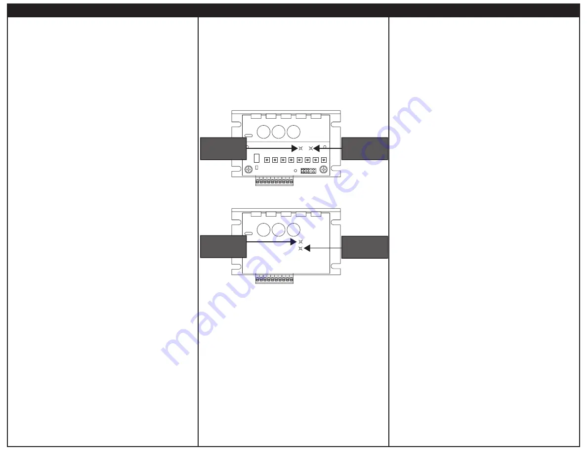
A1
MOTOR
Green Status
LED
Red Status
LED
BOTTOM BOARD
MOTOR
CL
REGEN
CL
FWD
SPEED
REV
SPEED
FB
OFFSET
FB
GAIN
BAND
DEAD
ERROR
GAIN
A1
MOTOR
POWER
CUR LMT
Curr
en
t Limit
LED
P
o
wer LED
TOP BOARD
Current Limit (CURR LIMIT):
Red LED turns on whenever the drive reaches current limit.
Power (POWER):
Green LED turns on whenever DC source voltage is applied to the drive.
Status LEDs
- Over Voltage: Green and red LEDs flash quickly.
Status LEDs
- Over Voltage: The source voltage is too high (greater than 32 VDC).
Status LEDs
-
Under Voltage: Green LED flashes slowly. Motor output is disabled.
Status LEDs
-
Under Voltage: The source voltage is too low (less than 7.5 VDC).
Status LEDs
-
Over Temperature: Green LED flashes quickly. Motor output is disabled.
Status LEDs
-
Over Temperature: The ambient temperature is too high (greater than 55°C).
Status LEDs
-
Thermal Foldback: Red LED flashes quickly. Ambient temperature reached 75°C. Drive
Status LEDs
- Thermal Foldback:
will lower current limit un�l the ambient temperature lowers to
Status LEDs
- Thermal Foldback:
an acceptable opera�ng temperature.
BOTTOM BOARD LEDS
TOP BOARD LEDS
LEDs
- Verify that no foreign conduc�ve material is present on the printed circuit board.
1. If using a speed adjust poten�ometer, turn it fully counterclockwise (CCW). If using an analog signal,
1.
set it for 0 VDC.
2. Apply the DC source voltage.
3. Close the Enable switch.
4. Command a posi�on using the posi�on poten�ometer or analog signal. The motor should move to
4.
the commanded posi�on.
5. Remove the DC source voltage.
STARTUP
Startup
250-0460 rev 2
Copyright 2019 by American Control Electronics® - All rights reserved. No part of this document may
be reproduced or retransmi�ed in any form without wri�en permission from American Control
Electronics®. The informa�on and technical data in this document are subject to change without
no�ce. American Control Electronics® makes no warranty of any kind with respect to this material,
including, but not limited to, the implied warran�es of its merchantability and fitness for a given
purpose. American Control Electronics® assumes no responsibility for any errors that may appear in
this document and makes no commitment to update or to keep current the informa�on in this
document.


