background image

3. Maintenance Procedure

14

3

Open the maintenance covers.

4

Clean the media sensor.

5

Once cleaning is complete, close the cover, then press the [ENTER] key.

Media Holder Cleaning

• Turn off the main power and unplug the power cable before carrying out maintenance.

• Do not allow liquids to get inside the product. Otherwise there is a risk of failure, electric shock,

or fire.

Continuing to use the dirty platen will prevent proper feeding of the media. It will also cause dried ink and
attached dust to rub against the head nozzle surface and lead to print defects (e.g., nozzle clogging,
deflection).

Media holder

• For heavy soiling, wipe using a soft cloth soaked in dilute detergent and thoroughly wrung out.

Jam Sensor Cleaning

The jam sensor is located on the side of the UV-LED unit on the right side of the carriage. If ink stains or dust
accumulate in the sensor unit, it may cause a media jam. Clean it with paper towels.

1

On the LOCAL mode screen, select [MENU] > [Maintenance], then press the [ENTER] key.

• The Maintenance menu is displayed.

2

Select [Station] > [Carriage Out] > [Head Maint.], then press the [ENTER] key.

• The carriage moves to the maintenance space.

Summary of Contents for UCJV150

Page 1: ...You can also download the latest manual from official website MIMAKI ENGINEERING CO LTD https mimaki com D203178 27 Original instructions...

Page 2: ...Cleaning 12 Media Sensor Cleaning 13 Media Holder Cleaning 14 Jam Sensor Cleaning 14 Platen Cleaning 15 Cover Exterior Cleaning 16 When Not in Use for Extended Periods 16 4 Consumable Item Replacemen...

Page 3: ...3 Maintenance To ensure years of precise performance maintain this product periodically based on frequency of use Read the maintenance precautions thoroughly before maintaining this product...

Page 4: ...fter turning off the LED For heavy soiling wipe using a soft cloth soaked in dilute detergent and thoroughly wrung out Pay close attention to ventilation and be sure to wear safety glasses gloves and...

Page 5: ...2 Soak up ink with a paper towel Cleaning the Mist Filter P 11 Clean the ink discharge channel Ink Discharge Channel Cleaning P 12 Clean the platen Platen Cleaning P 15 Clean the cover exterior Cover...

Page 6: ...mixed in the ink may cause nozzle clogging If the ink bottle is partially used tilt it slowly until the ink bottle is upright Wiper Cleaning The wiper wipes off ink adhering to the print head nozzle...

Page 7: ...ng stick moistened with maintenance liquid Wipe off the maintenance liquid Make sure none remains Wiper Bracket Replace dirty or warped wipers with new ones Wiper Replacement P 19 6 Clean the wiper sl...

Page 8: ...r towel once a week Doing so may result in leaking ink Do not remove the absorbent material in the absorbent material case Doing so may result in leaking ink 9 Once cleaning is complete close the cove...

Page 9: ...ght to correct the tilt 6 Close the front cover then press the ENTER key NCU Cleaning The NCU uses a sensor to monitor the ink droplets ejected from the print head nozzles Continuing to use the dirty...

Page 10: ...inuing to use the dirty carriage underside will rub dried ink and attached dust on to the media resulting in contaminated prints The print head uses an extremely delicate mechanism Take great care whe...

Page 11: ...he print head sides dark red area using a cleaning stick Never touch the nozzle surface Clean using a cleaning stick or soft cloth Never touch the print head nozzle surface 6 Once cleaning is complete...

Page 12: ...5 Clean the filter Remove the filter and press down on it with a paper towel to remove dirt Wipe off the dirt adhering to the filter case Replace the mist filter if it gets very dirty for example due...

Page 13: ...cap 5 Close the front cover then press the ENTER key Pump tube ink discharge channel below the cap washing starts Media Sensor Cleaning Media sensors are located on the rear cover and carriage unders...

Page 14: ...d ink and attached dust to rub against the head nozzle surface and lead to print defects e g nozzle clogging deflection Media holder For heavy soiling wipe using a soft cloth soaked in dilute detergen...

Page 15: ...Wipe off the ink and dust with a paper towel moistened with maintenance fluid Clean After the Wipe off the maintenance liquid Clean the jam sensor unit 5 Once cleaning is complete close the cover the...

Page 16: ...allow liquids to get inside the product Otherwise there is a risk of failure electric shock or fire For heavy soiling wipe using a soft cloth soaked in dilute detergent and thoroughly wrung out When...

Page 17: ...maintenance liquid and fill it until it almost overflows from the cap 9 Close the front cover then press the ENTER key Print nozzle washing starts The elapsed time is displayed on the display Nozzle...

Page 18: ...ot leave media loaded on the platen This may leave irregularities or ripples in the media When this product is not in use raise the clamp lever to separate the pinch rollers from the grid rollers Leav...

Page 19: ...t maintains a count of the number of wiping cycles The Replace Wiper message appears when a preset count is reached Replace dirty or warped wipers with new ones 1 Replace Wiper appears on the display...

Page 20: ...is very dirty or if ink drips on to the media replace with a new cap absorber 1 The Replace Cap Absorber message appears on the display 2 On the LOCAL mode screen select MENU Maintenance then press th...

Page 21: ...placement is complete move the wiper back to the rear by hand 10 Close the front cover then turn on the power Check to confirm that the carriage returns to the station Mist Filter Replacement Check th...

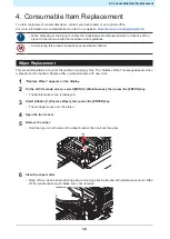
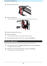
Page 22: ...nsert until it clicks into place and confirm that the tabs are engaged 7 Once replacement is complete close the cover then press the ENTER key LED Glass Replacement Replace with new LED glass if the i...

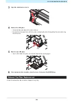
Page 23: ...ly too much force when unclipping the tabs Disregarding this precaution may break the tabs Claw 5 Mount a new LED glass Insert until it clicks into place and confirm that the tabs are engaged 6 Once r...

Page 24: ...ust fan filter into the space under the tabs of the exhaust fan box Exhaust fan box Exhaust fan filter 3 Mount the exhaust fan box Insert the tabs of the exhaust fan box into the slits of the machine...

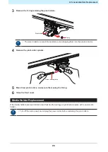
Page 25: ...roduct interior 4 Remove the pinch roller spindle Pinch roller spindle 5 Mount new pinch rollers and secure them using the O ring 6 Close the front cover Media Holder Replacement If the media holder b...

Page 26: ...Replacement 26 1 Open the maintenance covers 2 Remove the side screw and detach the media holder stopper 3 Remove the media holder 4 Remove the sliders from the media holder Be careful to avoid mispl...

Page 27: ...n 7 Secure the media holder stopper with the screw 8 Close the maintenance covers Media Cutter Replacement Replace cutters when blades are chipped or blunt Avoid touching the cutter blade Failure to d...

Page 28: ...the product contact an industrial waste disposal operator or dispose of the product in accordance with the local laws and regulations Waste Ink Tank Replacement Ink used during head cleaning and other...

Page 29: ...p If there is no discrepancy replace dispose of the waste ink tank referring to Replacing the Waste Ink Tank P 29 3 On the LOCAL mode screen select MENU Maintenance then press the ENTER key The Mainte...

Page 30: ...de out 5 Attach the cap to the removed waste ink tank and use tape to prevent leakage of waste ink When disposing of the product contact an industrial waste disposal operator or dispose of the product...

Page 31: ...ntric blade for reflective sheets SPB 0006 Eccentric blade for fluorescent sheets SPB 0007 Low pressure eccentric blade for PVC sheets SPB 0030 Eccentric blade for thick rubber sheets SPB 0084 For mor...

Page 32: ...PEN LINE RUBBER FOR 150 75 SPC 0773 PEN LINE SPONGE FOR 300 150 160 SPC 0775 PEN LINE SPONGE FOR 300 150 130 SPC 0776 PEN LINE RUBBER FOR 150 107 SPC 0777 PEN LINE RUBBER FOR 150 75 SPC 0778 For more...

Page 33: ......

Page 34: ......

Page 35: ...Requests for Care and Maintenance December 2021 MIMAKI ENGINEERING CO LTD 2182 3 Shigeno otsu Tomi shi Nagano 389 0512 JAPAN D203178 27 20122021...

Page 36: ...MIMAKI ENGINEERING CO LTD 2017 AT FW 3 1...

Reviews:

Related manuals for UCJV150