
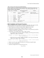


Disk Brake Maintenance
PELLERIN MILNOR CORPORATION
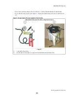
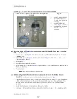
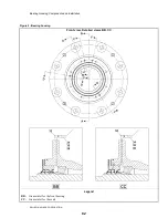
Figure 6: The Adjustment between the Brake Rod and the Air Cylinder
Schematic Views of Different Conditions
Legend
AC. Air cylinder (
Figure 5
, item 4)
BC. Brake cylinder (
Figure 5
, item 1)
VS. Slot to see the nuts (
Figure 5
, item 6)
A.
Before travel adjustment -- Rods not locked by nuts (
Figure 5
, item 5)
B.
After travel adjustment -- the brake released (See
Section 6.2
)
C.
Brake applied--NEW pads (See
Section 6.1
)
D.
Brake applied--OLD pads
E.
This will occur if you apply the brake with the hydraulic line removed
TN. Rod travel, new pads
TO. Rod travel, very worn pads
TT. Full travel with the hydraulic line removed
M1 First mark at the view slot -- the brake released
M2a. Second mark--one possible position -- the brake applied
M2b. Second mark-- a different position -- the brake applied
AT. Air tubing (See
Figure 1
,1). Air releases the brake.
S.
Spring applies the brake
.
69
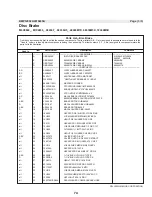
Summary of Contents for 48040M7K
Page 2: ......
Page 8: ......
Page 9: ...Safety 1 5 ...
Page 43: ...Installation 2 39 ...
Page 56: ......
Page 57: ...Drive 3 53 ...
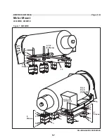
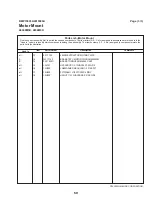
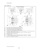
Page 59: ...Drive Components and Belt Installation PELLERIN MILNOR CORPORATION Figure 2 Detailed views 55 ...
Page 93: ...Frame and Tilt 4 89 ...
Page 101: ...Hydraulic Assemblies 5 97 ...
Page 110: ......
Page 111: ...Door Assemblies 6 107 ...
Page 125: ...Water and Steam 7 121 ...
Page 137: ...Chemical 8 133 ...
Page 142: ......
Page 143: ...Control and Sensing Assemblies 9 139 ...
Page 149: ...Dimensional 10 145 ...
Page 150: ......
Page 151: ...147 ...