


Disk Brake Maintenance
PELLERIN MILNOR CORPORATION
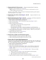
You must have the necessary kit for the overhaul of your machine. Refer to the brake parts
document in your machine's manual.
1. Remove power from the machine (see Notice P1).
2. Get access to the caliper halves (see
Section 2
).
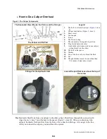
3. Do an overhaul on each caliper:
a. Remove and discard the connection O-rings (
Figure 2
, item 7) on the caliper bodies.
b. Apply compressed air to the fitting for the hydraulic inlets (see
Figure 2
, item 8) to push
the pistons out.
c. Replace the piston O-rings (
Figure 2
, item 6).
d. Put the pistons in the caliper body. Carefully tap the pistons with a wood or rubber
hammer to install it.
e. Replace the connection O-rings. (
Figure 2
, item 7)
f. Replace the friction pads (see
Section 2
).
4. Replace the caliper halves as specified in
Section 2
.
5. Bleed the brake circuit (see
Section 4
).
6. Supply electrical power to the machine.
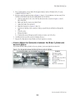
4.
How to Change Hydraulic Fluid and Remove (Bleed) Air from the
Brake Circuit
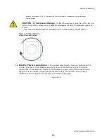
4.1.
Risks and Precautions
WARNING 3 : Risk of injury
—Machine power must be on for these procedures.
• Stay away from operating mechanisms.
CAUTION 4 : Risk of injury and damage
—This procedure releases pressurized brake
fluid.
• Keep brake fluid out of your eyes and mouth. Wear eye protection.
• Follow procedures carefully to prevent damage to the face of the disk or the pistons.
CAUTION 5 : Risk of malfunction .
—Air in hydraulic fluid will compress. Compressed
air in the brake line will cause brake malfunctions.
• Remove (bleed) air from the brake circuit before you operate the machine.
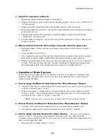
4.2.
Requirements
—These personnel and items are necessary for this procedure:
• two technicians
• an 8-ounce container of new brake fluid
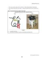
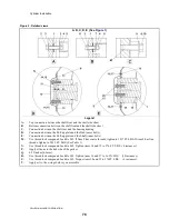
• Alternative procedures to remove air and used brake fluid:
» a suction pump (faster procedure) (see
Figure 3
)
» with pressure in the hydraulic cylinder and gravity (see
Figure 4
)
Tip:
The Vacula suction pump can do the work more quickly than by gravity and pressure in the
hydraulic cylinder. It is also cleaner because all of the hydraulic fluid goes into the container
supplied. It helps you not spill the hydraulic fluid.
65
Summary of Contents for 48040M7K
Page 2: ......
Page 8: ......
Page 9: ...Safety 1 5 ...
Page 43: ...Installation 2 39 ...
Page 56: ......
Page 57: ...Drive 3 53 ...
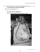
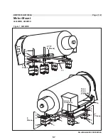
Page 59: ...Drive Components and Belt Installation PELLERIN MILNOR CORPORATION Figure 2 Detailed views 55 ...
Page 93: ...Frame and Tilt 4 89 ...
Page 101: ...Hydraulic Assemblies 5 97 ...
Page 110: ......
Page 111: ...Door Assemblies 6 107 ...
Page 125: ...Water and Steam 7 121 ...
Page 137: ...Chemical 8 133 ...
Page 142: ......
Page 143: ...Control and Sensing Assemblies 9 139 ...
Page 149: ...Dimensional 10 145 ...
Page 150: ......
Page 151: ...147 ...