


Ê
Preventive Maintenance Items
Ê
Testing Belt Tension
NOTE: Use the “Initial Tension” column (Table below) when ad-
justing belts that have never been used. Use the “Final Tension”
column when adjusting belts that have been used.
Check belt tension when replacing and adjusting drive train com-
ponents. Belt tension testing tool (Milnor
®
part number 30T001),
straight edge, and Belt Tension Tables are required when setting belt
tensions. Do not refer to instruction sheet provided with tension
testing tool. Check tensions for new belts according to the following
schedule:
•
After 24 hours of operation (three eight-hour days)
•
After 80 hours of operation (ten eight-hour days)
•
After 160 hours of operation (twenty eight-hour days)
1. Move upper O-ring on the tension testing tool to the uppermost position (resting against the bottom edge of
sliding cap).
2. Determine deflection for the main drive belt (see FIGURE 5 for the belt location and Table for the setting
range). Move lower O-ring to the correct setting (inches or centimeters) on scale. Read the bottom edge of
the O-ring.
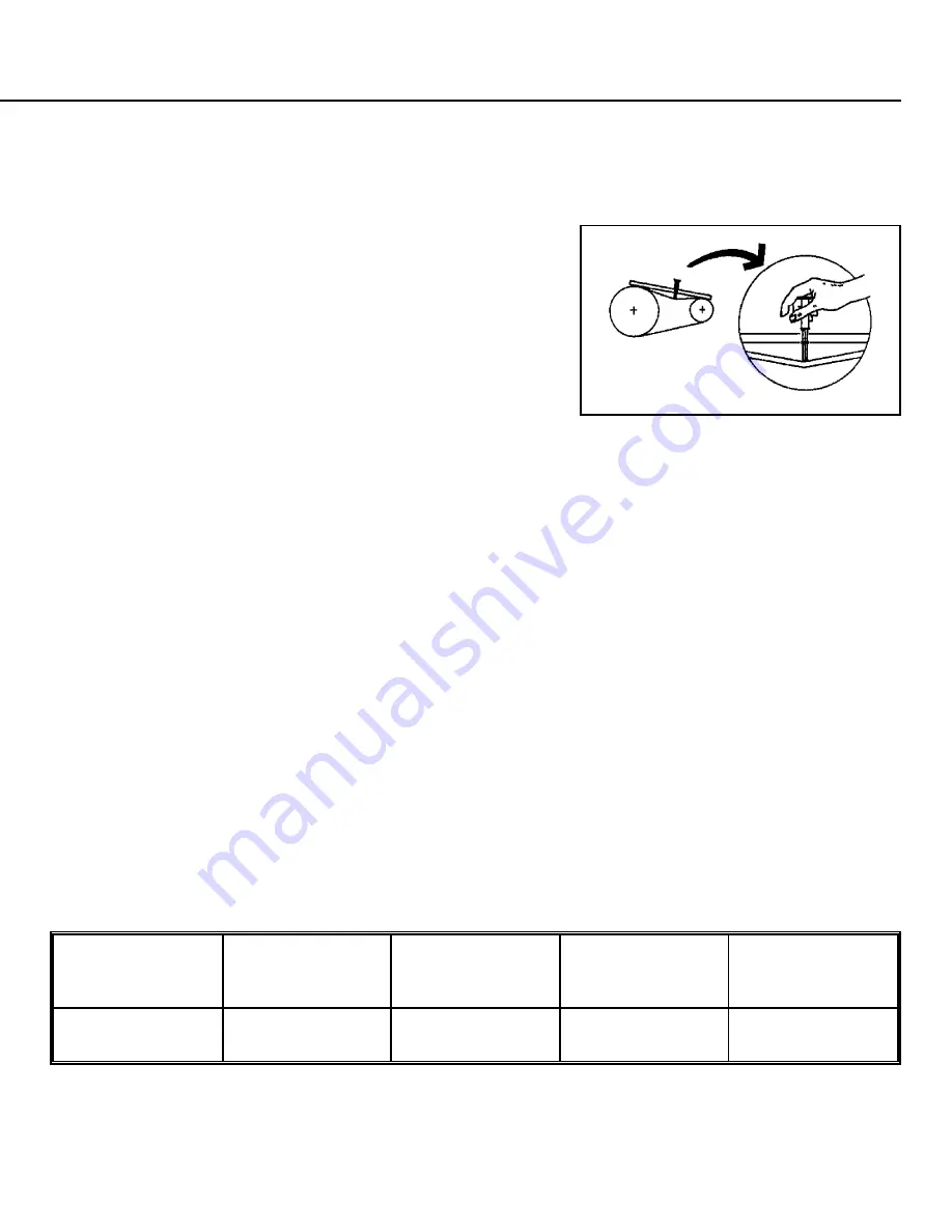
3. Place a straight edge along the top edge (pulley to pulley) of the belt. Depress the tension testing tool by slid-
ing the cap against the middle of the belt span until the bottom edge of the lower O-ring aligns with the
straight edge as shown in FIGURE 6.
4. Read the top edge of the upper O-ring position and determine if it is within the specified range. If the readings
are below the specified range, tighten the belt. If the readings are above the specified range, loosen the belt.
Adjust the belt and repeat steps one through four until tension is within the specified range.
Ê
Replacing Belts
Remove motor drive belt by loosening the threaded jacking rods that determine the belt tension for the pulley.
Do not force belts off by prying and turning pulley. Check belt tension and pulley alignment after replacing the
belts.
Ï
Table — Main Drive Belt Tension Specifications
Model
Cycle
Belt Deflection
(centimeters)
Initial Tension
pounds
(kilograms)
Final Tension
pounds
(kilograms)
30022H7J
30022H8J
All
24/64
(0.95)
6.7—9.8
(3.0—4.4)
5.2—7.6
(2.4—3.4)
Î
FIGURE 1
(MSSM0712AE)
Î
Water Seal Grease Point
Î
FIGURE 2
(MSSM0712AE)
Î
Main Bearing Housing
Vent (1) and Oil Fill (2)
Î
FIGURE 3
(MSSM0712AE)
Î
Bearing Housing Oil Drain
Plug (1), Leak-off (2), and
Seal Grease Relief (3)
Î
FIGURE 4
(MSSM0712AE)
Î
Inlet Valve Strainers
Î
FIGURE 5
(MSSM0712AE)
Î
Drive Train
Î
FIGURE 6
(MSSM0712AE)
Î
Setting Belt Tension
Summary of Contents for 30022H7 Series
Page 4: ......
Page 6: ......
Page 8: ......
Page 10: ......
Page 11: ...Section 1 Service and Maintenance ...
Page 20: ... 3 4 3 3 4 4 0 0 12 0 2 ...
Page 22: ... 00 3 4 8 4 8 3 9 0 01 0 12 0 2 ...
Page 44: ......
Page 45: ...Section 2 Drive Assemblies ...
Page 53: ...Section 3 Shell Door and Assemblies ...
Page 60: ......
Page 61: ...Section 4 Water and Steam Piping and Assemblies ...
Page 68: ......
Page 69: ...Section 5 Chemical Supply Devices ...