

7ML19981CX01
ILE-61 Sensing Head – INSTRUCTION MANUAL
Page 9
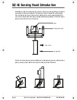
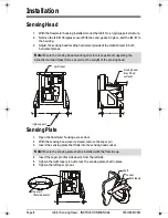
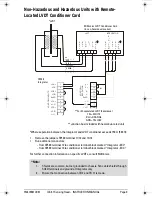
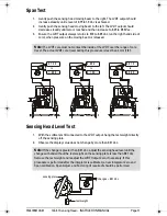
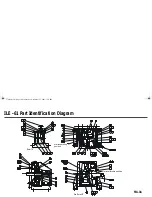
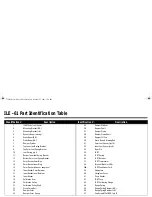
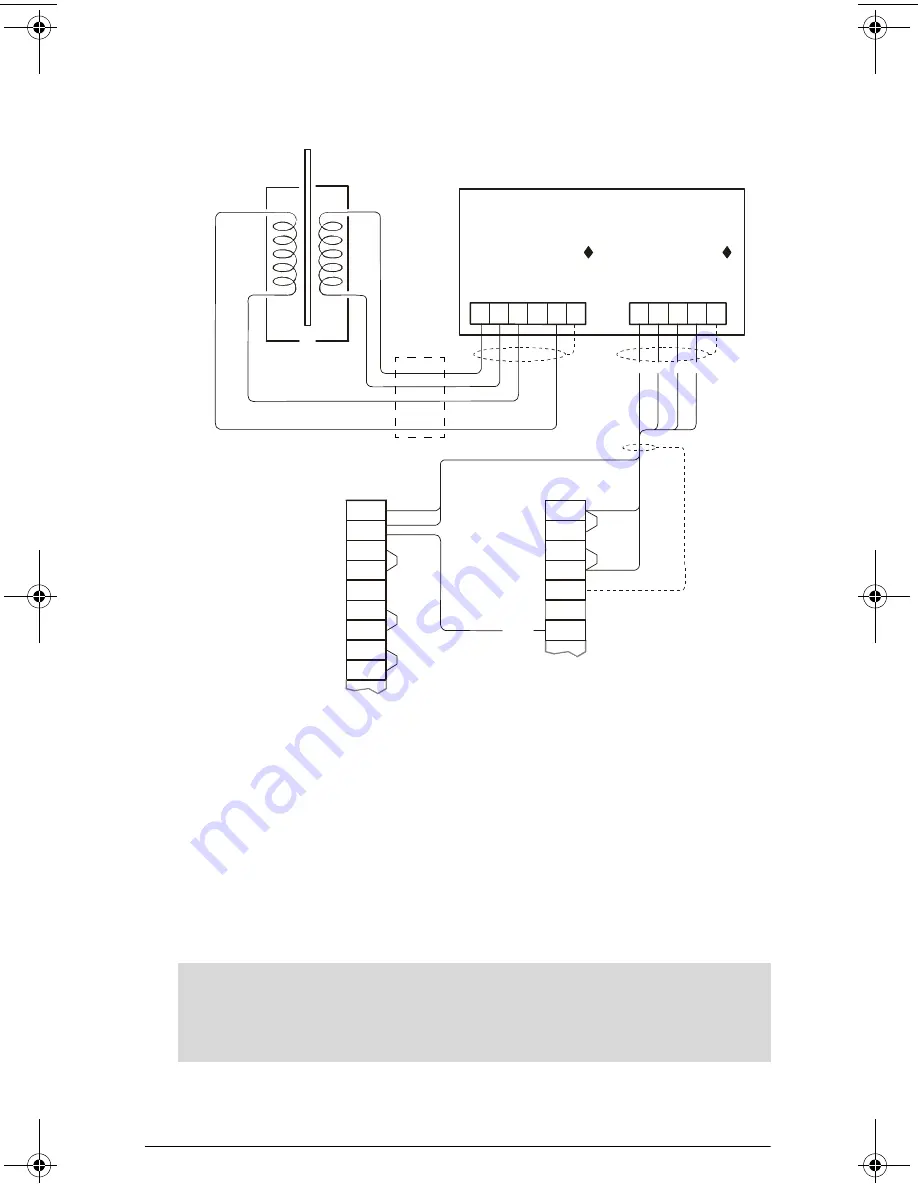
Non-Hazardous and Hazardous Units with Remote-
Located LVDT Conditioner Card
*Where separation between the Integrator and LVDT conditioner exceeds 150 m (500 ft):
•
Remove the jumpers SF500 terminal 11/12 and 13/14
•
Run additional conductors:
- from SF500 terminal 12 to conditioner terminal block marked “InteEXC”
- from SF500 terminal 13 to conditioner terminal block marked “Integrator –EXC”
For further connection information on specific LVDTs, consult Milltronics.
11
14 1
2
11
1
6
12
2
7
13
3
8
14
15
16
17
4
9
5
10
18
V+
S+
S-
V-
SHLD
-L
O
A
D
C
E
LL-
EXC
IT
A
T
IO
N
LCA+
LCA-
LCB+
LCB-
SHLD
LCC+
SIG
LCC-
COM
LCD+
CNST
LCD-
SHLD
-L
O
A
D CE
LL
I
N
P
U
T
S
-
E
X
C
+
E
X
C
+
E
X
C
-
E
X
C
-
C
O
M
S
I
G
/
C
O
M
C.
T.
S
I
G
-
S
H
L
D
S
H
L
D
S
I
G
+
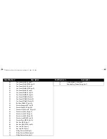
LVDT
INTEGRATOR
RED
BLUE
YELLOW
GREEN
SF500
Integrator
Milltronics LVDT Conditioner Card
(in non-hazardous location)
*
**For Encapsulated LVDT (hazardous)
YEL = WHITE
BLU = ORANGE
GRN = YELLOW
**Junction box included with hazardous-rated unit.
*LVDT
**
♦
Note:
1.
Shields are common, but not grounded to chassis. Run cable shields through
SHLD terminals and ground at Integrator only.
2.
Ensure that connection between TB 2 and TB 17 is made.
376draft1.fm Page 9 Wednesday, November 21, 2001 1:54 PM
Siemens Industrial
Summary of Contents for ILE-61
Page 1: ...ILE 61 SENSING HEAD November 2001 LE 61 SEINSIING HEA Instruction Manual PL 376...
Page 24: ......
Page 25: ...Notes...
Page 26: ...Notes...
Page 27: ......
Page 28: ...7ML19981CX01...


