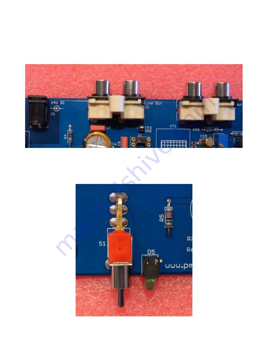
11. Install power jack J1, input jack J4, and line out jack J2
Install the jacks on the rear edge of the PCB. J2 and J4 snap into the PCB, but J1 may need
to be held in with tape (or your fingers) when you solder it in.
As before, make sure the parts are fully seated on the PCB before completely soldering them
in!
12. Install the "power on" LED D5
The LED is installed like the small capacitors. Just make sure it's pointed off the edge of the
PCB!


