Miller XMT 450 CC Technical Manual Download Page 47

PRE-POWER CHECKS

TM-257 220 Page 43

XMT 450 CC/CV

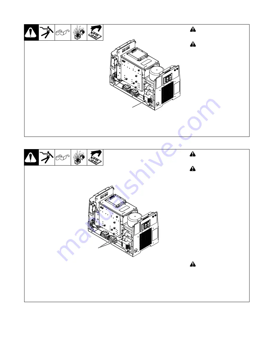
10-7. Input Contactor W1

255 761-A

!

Read and follow safety
information in Section 10-1
before proceeding.

!

Wear an earth grounded
wrist strap when performing
pre-power  and power off
checks. Remove wrist strap
before performing any
checks or procedures with
power applied to the ma-
chine.

1

Verify normally-open contacts
of W1 are not stuck shut by
measuring with DVM set to
ohms.

2

Check resistance of W1 coil.
It should measure
approximately 7 ohms.

Input Contactor W1

10-8. Tank Capacitors C1, C2

Ref. 255 761-A

!

Read and follow safety
information in Section 10-1
before proceeding.

!

Wear an earth grounded
wrist strap when performing
pre-power  and power off
checks. Remove wrist strap
before performing any
checks or procedures with
power applied to the ma-
chine.

1

Verify C1 and C2 are not
shorted by measuring with
DVM set to ohms.

.

This is not a conclusive test.
For best results, use a
capacitor tester to check
capacitance.

2

Check capacitance of C1 and
C2. They are in parallel and
should measure
approximately .68 

μ

F.

Disconnect lead at
interconnect PC2 for proper
measurement.

!

Pre-power  checks are now
complete. Remove earth
grounded wrist strap before
performing any checks or
procedures with power ap-
plied to the machine.

Tank Capacitors C1, C2

Summary of Contents for XMT 450 CC

Page 1: ...elding Power Source XMT 450 CC CV TM 257 220B 2015 03 Eff w Serial Number MC100104A Processes Description Multiprocess Welding File MULTIPROCESS Visit our website at www MillerWelds com R 400 Volt Mod...

Page 2: ...14 4 7 Electrical Service Guide 15 4 8 Connecting Input Power 16 SECTION 5 GENERAL OPERATION 18 5 1 Front Panel 18 5 2 Mode Switch Settings 19 SECTION 6 GTAW OPERATION 20 6 1 Typical Connection For GT...

Page 3: ...10 11 50 10 13 Inverter Control Board PC1 Testing Information Use With Section 10 14 52 10 14 Inverter Control Boards PC1 Test Point Values 53 10 15 Inverter Control Board PC1 Diagnostic LEDs 54 10 1...

Page 4: ......

Page 5: ...live unit use the one hand method Do not put both hands inside unit Keep one hand free D Disconnect input power conductors from deenergized supply line BEFORE moving a welding power source SIGNIFICAN...

Page 6: ...in formationat the beginning of the manual and in each section D Perform maintenance and service according to the Technical Manual industry standards and national state and local codes 1 3 California...

Page 7: ...information Safe37 2012 05 Wear dry insulating gloves Do not touch electrode with bare hand Do not wear wet or damaged gloves Safe2 2012 05 Protect yourself from electric shock by insulating yourself...

Page 8: ...2 05 Always wear long sleeves and button your collar when servicing unit Safe28 2012 05 After taking proper precautions as shown connect power to unit Safe29 2012 05 Do not use one handle to lift or s...

Page 9: ...2012 05 60 Always lift and support unit using both handles Keep angle of lifting device less than 60 degrees Use a proper cart to move unit Safe44 2012 05 2 2 Miscellaneous Symbols And Definitions A...

Page 10: ...creases the output amperage at the start of a weld eliminating electrode sticking in CC and Stick Welding Modes see Sections 8 2 and 8 3 3 2 Arc Controls DIG control allows the arc characteristics sof...

Page 11: ...c striking and stabilizing devices as part of the welding circuit may not be a major contributor to the EMF See the Owner s Manuals for all components of the welding circuit for additional EMF exposur...

Page 12: ...s opens output stops and cooling fan runs Wait fifteen minutes for unit to cool Reduce amperage or duty cycle before welding NOTICE Exceeding duty cycle can damage unit and void warranty Overheating...

Page 13: ...lding power source Curves of other set tings fall between curves shown AMPERAGE VOLTAGE CC Mode VOLTAGE CV MODE AMPERAGE 0 20 40 60 80 100 0 100 200 300 400 500 600 700 MAX MIN 252 918 A 252 919 A 0 2...

Page 14: ...e NEC Article 511 or CEC Section 20 1 Lifting Forks Use lifting forks to move unit Extend forks beyond opposite side of unit 2 Lifting Handles Use handles to lift unit 3 Hand Cart Use cart or similar...

Page 15: ...20 3 30 2 35 1 50 1 0 60 1 0 60 150 3 30 3 30 2 35 1 50 1 0 60 2 0 70 3 0 95 3 0 95 200 3 30 2 35 1 50 1 0 60 2 0 70 3 0 95 4 0 120 4 0 120 250 2 35 1 50 1 0 60 2 0 70 3 0 95 4 0 120 2x2 0 2x70 2x2 0...

Page 16: ...nal and copper bar are clean Tools Needed 3 4 in 19 mm 4 2 3 Do not place anything between Incorrect Installation 1 weld cable terminal and copper bar 4 4 Remote 14 Receptacle Information A J B K I C...

Page 17: ...ntary Protectors Ref 257 348 A 1 115 V 7 Amp AC Receptacle 2 Supplementary Protector CB1 3 Supplementary Protector CB2 CB1 protects duplex receptacle CB2 protects 24 volts AC portion of Remote 14 rece...

Page 18: ...to Gas In fitting Connect hose coupler to torch Connect one end of gas hose to hose coupler Connect remaining end of gas hose to Gas Out fitting Operation The gas solenoid controls gas flow during th...

Page 19: ...rating to be less than the rating of the circuit protection device All components of the circuit must be physically compatible See NEC articles 210 21 630 11 and 630 12 50 60 Hz Three Phase Input Volt...

Page 20: ...TM 257 220 Page 16 XMT 450 CC CV 4 8 Connecting Input Power Tools Needed 5 16 in 3 8 1 4 9 7 10 11 L1 L2 L3 GND PE Earth Ground 1 Input5 2013 04 Ref 803 766 C 257 348 A 2 4 3 6 5 7 L1 L2 L3...

Page 21: ...ough strain relief Tighten strain relief S Use large strain relief for input conductor size 8 and larger S Use small strain relief with reducing washers for input conductor size 10 3 Welding Power Sou...

Page 22: ...1 Remote 14 Receptacle 2 Left Display 3 Right Display The meters display the actual weld output values after arc initiation and remains dis played for approximately three seconds after the arc is bro...

Page 23: ...GTAW Remote 14 Amps Panel Amps Scratch Start TIG GTAW Remote 14 Amps Panel Amps MIG GMAW Remote 14 Volts Volts Pulsed MIG GMAW P Remote 14 N A Arc Length 0 100 Stick SMAW CAC A Remote 14 Amps Panel A...

Page 24: ...f power before making con nections 1 Foot Control 2 Positive Weld Output Terminal 3 Remote 14 Receptacle Connect desired remote control to Remote 14 receptacle if required 4 Gas In Connection Optional...

Page 25: ...osition as shown The open circuit voltage is shown in the Left Display Preset amperage is shown in the Right Display Operation The Adjust Control is used to set desired preset amperage If a remote con...

Page 26: ...desired preset amperage A remote control is required to turn on the weld output To start welding momentarily depress out put switch Touch tungsten electrode to workpiece at weld start point Slowly li...

Page 27: ...tion as shown The preset amperage is shown in the Right Display Operation The Adjust Control is used to set desired preset amperage A remote control is required to turn on the weld output If the remot...

Page 28: ...eptacle 2 Positive Weld Output Terminal 3 Negative Weld Output Terminal 4 Ground Cable to Workpiece 5 Workpiece 6 Gun 7 Wire Feeder 8 Gas Hose 9 Gas Cylinder Use of shielding gas is dependant on Wire...

Page 29: ...st Control is used to set desired preset voltage The preset voltage can be adjusted re motely at the wire feeder if the feeder has a voltage control This voltage con trol will override the Adjust Cont...

Page 30: ...nal 4 Negative Weld Output Terminal 5 Ground Cable to Workpiece 6 Workpiece 7 Gun 8 Wire Feeder 9 Gas Hose 10 Gas Cylinder Use of shielding gas is dependant on Wire Type The connection diagram illustr...

Page 31: ...Right Display 4 Adjust Control Setup For typical system connections refer to Section 7 3 Rotate Mode Switch to PULSED MIG posi tion as shown Left and Right Display will show PPP PPP Operation This uni...

Page 32: ...ld Output Terminal 3 Ground Cable to Workpiece 4 Workpiece 5 Voltage Sensing Clamp 6 Gun 7 Gun Trigger Receptacle 8 Wire Feeder 9 Gas Hose 10 Gas Cylinder Use of shielding gas is dependant on Wire Typ...

Page 33: ...Display toggles between open cir cuit voltage and preset voltage Operation The Adjust Control is used to set desired preset voltage The Left Display toggling momentarily pauses while the preset volta...

Page 34: ...efore making con nections 1 Electrode Holder Carbon Arc For CAC A process connect carbon arc cutting torch to to positive weld output ter minal 2 Electrode Holder 3 Positive Weld Output Terminal 4 Rem...

Page 35: ...n 3 is se lected remote control preset will be displayed in the amperage window See section 8 5 for more information regarding Alternate Configuration Functionality Adaptive Hot Start automatically in...

Page 36: ...tive remote controls will be ignored and amperagewill operate in panel only control See section 8 5 for more information re garding Alternate Configurations Adaptive Hot Start automatically increases...

Page 37: ...en configuration 2 is selected Stick mode operates in Panel Only control meaning any remote control that is plugged into the remote 14 control will be ignored and have no effect on the output When Sti...

Page 38: ...rs C3 C4 C5 C6 PC5 8 Inductor L3 15 Inductor L4 SR1 Ribbon Cable 24 PC 2 9 PC3 PM1 PM2 PC1 A Block Diagram 2 3 DC Bus Voltage Feed back 20 Supplementary Protector Gas Solenoid Fan Motor FM2 23 Fan Mot...

Page 39: ...nsformer 35 36 38 Positive Weld Output Terminal 40 Negative Weld Output Terminal 39 Electrode Stabilizer 37 Work Output Diodes Optional Series Capacitor C1 C2 Current Transducer Weld Voltage Feedback...

Page 40: ...face board PC3 Energizes input contactor W1 upon com pletion of pre charge cycle Provides interface between primary and secondary heatsink thermistors and in verter control board PC3 20 Supplementary...

Page 41: ...hing any parts Before applying power to unit complete the following checks to avoid causing further damage Although control board PC1 and power interconnect board PC2 are briefly checked here more com...

Page 42: ...re the DC voltage across the screw terminals on PC2 as shown until voltage drops to near 0 zero volts If the capacitor voltage does not drop to near zero after sev eral minutes use a bleeder re sistor...

Page 43: ...th 6 internal diodes 2 diodes for each phase SR1 is located between the right heat sink and the large vertical power interconnecting board PC2 1 Visually inspect SR1 for damage If there is visual evid...

Page 44: ...ace both PM1 and PM2 2 Check function of IBGT s in PM1 and PM2 with IGBT tester MILLER Part No 043 553 Disconnect gate lead Plug 3 from receptacle RC3 on Inverter Control board PC1 Connect tester to m...

Page 45: ...ly inspect components for damage If there is visual evidence of damage such as smoke debris or found to be defective using this procedure replace interconnect board 2 Check diodes D1 and D2 using diod...

Page 46: ...er diodes found to be defective using this procedure 2 First check across weld output terminals using diode check with DMM Look for diode drop of 1 to 3 VDC with leads connected as follows If measurem...

Page 47: ...ef 255 761 A Read and follow safety information in Section 10 1 before proceeding Wear an earth grounded wrist strap when performing pre power and power off checks Remove wrist strap before performing...

Page 48: ...ens Unit overheated and HELP 3 or HELP 5 screen is displayed Allow unit to cool with fans On see Section 10 10 Check repair or replace remote control Check coil voltage and connections of contactor W1...

Page 49: ...de Fault Description Probable Cause s Potential Solution s Help 1 Primary Power Cir cuit Over Current LED1 is lit on Inverter Control Board PC1 Primary IGBTs exceeded peak current limit of 350 amperes...

Page 50: ...temperat ure too high Move unit to a lower ambient temperature location Front panel display board PC3 malfunction Replace PC3 Help 8 Output Over Volt age Malfunction Output voltage exceeded 100 VDC fo...

Page 51: ...C3 C4 C5 and C6 R1 R6 R12 R13 Check resistors see Section 10 5 Gate lead wiring is incorrect Check gate lead wiring and repair or replace as needed Inverter Control board PC1 malfunction Replace PC1...

Page 52: ...fore applying power see Section 10 1 TM 257 220 Page 48 XMT 450 CC CV 10 11 Troubleshooting Circuit Diagram For Welding Power Source All Models Use With Section 10 12 E A B C D V1 R1 V2 R11 V7 V4 V5 V...

Page 53: ...Always check unit before applying power see Section 10 1 TM 257 220 Page 49 XMT 450 CC CV 256 909 A Test Equipment Needed V10 V11 R3 R8 V16 R4 R5 R6 R7 V15 V12 V13 V14...

Page 54: ...e 10 unless specified b Reference to circuit common lead 42 unless noted V1 565 VDC V2 400 VAC V3 24 VAC V4 V5 18 VAC V6 115 VAC V7 24 VAC after precharge V8 V9 24 VDC with fans running RC7 2 RC8 2 re...

Page 55: ...Always check unit before applying power see Section 10 1 TM 257 220 Page 51 XMT 450 CC CV Notes...

Page 56: ...818 C 255 763 A Measure voltage of input ca pacitors according to Section 10 2 and be sure voltage is near zero before touching any parts Be sure plugs are secure before test ing See Section 10 14 fo...

Page 57: ...put 5 volts DC reference voltage for thermistor 14 GND Circuit common referenced to chassis 15 Output Secondary side thermistor return 2 volts DC at 25 C thermistor temperature 16 GND Circuit common r...

Page 58: ...with respect to RC8 2 with fan motor FM1 running 2 Output Fan motor supply return RC9 1 Output Current transducer power 15 volts DC 2 Input Weld current feedback 1 volt DC per 100 amperes of weld out...

Page 59: ...Always check unit before applying power see Section 10 1 TM 257 220 Page 55 XMT 450 CC CV Notes...

Page 60: ...0 17 255 761 A 233 080 D Measure voltage of input ca pacitors according to Sec tion10 2 and be sure voltage is near zero before touching any parts Be sure plugs are secure before testing See Section 1...

Page 61: ...4 2 Not used 3 282 volts DC with respect to pin RC2 6 4 Reference for pin RC2 1 5 Not used 6 Reference for pin RC2 3 RC7 1 2 3 4 5 6 7 9 10 11 12 13 Not used 8 400 volts AC with respect to pin RC7 14...

Page 62: ...10 19 243 575 B 255 763 A Measure voltage of input capacitors according to Section 10 2 and be sure voltage is near zero before touching any parts Be sure plugs are secure before ap plying power See...

Page 63: ...able 5 volts DC fan on 28 volts DC fan off 10 Not Used 11 Input Main transformer overcurrent detect 0 volts DC OK 5 volts DC T1 primary current HELP 1 12 Not Used 13 Output 5 volts DC reference voltag...

Page 64: ...ignal common E Input Input signal from remote command 0 to 10 volts DC F Output Current feedback 1 volt DC per 100 amperes of weld output G GND 14 pin remote accessory power return H Output Voltage fe...

Page 65: ...connect and lockout tag out input power before re moving cover Follow this procedure to configure the unit for low open circuit voltage OCV operation in Stick and Scratch Start TIG modes OCV is reduce...

Page 66: ...seconds and then jump to 282 volts DC when contactor W1 engages Compare voltages on the bus capacitors the difference between the voltages must be less than 30 volts at all times Be ready to turn unit...

Page 67: ...hs Replace Damaged Or Unreadable Labels Replace Cracked Torch Body Repair Or Replace Cracked Cables Repair Or Replace Cracked Cables And Cords Clean And Tighten Weld Connections 6 Months Blow Out Insi...

Page 68: ...TM 257 220 Page 64 XMT 450 CC CV Notes...

Page 69: ...e information The following is a list of all diagrams for models covered by this manual Model Serial Or Style Number Circuit Diagram Wiring Diagram XMT 450 CC CV 400 Volt MC100104A and following 256 9...

Page 70: ...TM 257 220 Page 66 XMT 450 CC CV Figure 12 1 Circuit Diagram For 400 Volt Models Effective With MC100104A And Following...

Page 71: ...TM 257 220 Page 67 XMT 450 CC CV 256 909 A...

Page 72: ...TM 257 220 Page 68 XMT 450 CC CV Figure 12 2 Wiring Diagram for XMT 450 CC CV 400 Volt Eff w MC100104A And Following 1 of 2...

Page 73: ...TM 257 220 Page 69 XMT 450 CC CV 256 916 C...

Page 74: ...TM 257 220 Page 70 XMT 450 CC CV Figure 12 3 Wiring Diagram for XMT 450 CC CV 400 Volt Eff w MC100104A And Following 2 of 2...

Page 75: ...TM 257 220 Page 71 XMT 450 CC CV 256 916 C...

Page 76: ...TM 257 220 Page 72 XMT 450 CC CV Notes...

Page 77: ...A And Following For OM 257 220 Revisions A Thru H TM 257 220B 2015 03 Eff w Serial Number MC100104A Arc Welding Power Source Processes Description Multiprocess Welding Visit our website at www MillerW...

Page 78: ...CTION 13 PARTS LIST Hardware is common and not available unless listed 5 6 7 8 1 2 3 4 13 14 15 16 9 10 11 12 21 22 23 24 17 18 19 20 30 31 32 33 25 28 29 38 39 40 41 34 35 36 37 46 47 48 49 42 43 44...

Page 79: ...TM 257 220 Page 75 XMT 450 CC CV 257 223 D 50 51 52 53 54 55 56 57 58 59 60 61 62 63 64 65 66 67 68 69 70 71 72 73 74 75 76 77 78 79 80 81 82 83 84 85 86 87 88 89 90 91 92 93 94 95 60...

Page 80: ...20 RT1 199 798 Thermistor NTC 30K OHM 25 Deg C 18 00In 2500V 1 21 201 531 Kit Diode Power Module 4 22 199 840 Bus Bar Diode 4 23 232 296 Resistor Capacitor Assy 2 C21 C24 180 877 Capacitor Assy 4 24...

Page 81: ...C Frict 1 69 CB2 083 432 Supplementary Pro Man Reset 1P 10A 250VAC Frict 1 70 256 890 Panel Rear W Studs 400V Prior to ME242508U 1 70 263 629 Panel Rear W Nut Inserts Aux Power 400V Eff w ME242508U 1...

Page 82: ...1 PLG 12 115 093 Housing Plug Pins Service Kit RC2 1 PLG 13 115 091 Housing Plug Pins Service Kit RC9 1 PLG 15 16 115 094 Housing Plug Pins Service Kit RC1 On PC4 5 2 When ordering a component origin...

Page 83: ...Notes...

Page 84: ...er Electric Mfg Co An Illinois Tool Works Company 1635 West Spencer Street Appleton WI 54914 USA International Headquarters USA USA Phone 920 735 4505 Auto Attended USA Canada FAX 920 735 4134 Interna...

Reviews: