background image

OM- 257 486 Page 1

SECTION 1 − SAFETY PRECAUTIONS - READ BEFORE USING

som 2013−09

7

Protect yourself and others from injury —


read, follow, and save these important safety precautions and operating instructions.

1-1.

Symbol Usage

DANGER! − Indicates a hazardous situation which, if
not avoided, will result in death or serious injury. The
possible hazards are shown in the adjoining symbols
or explained in the text.

Indicates a hazardous situation which, if not avoided,
could result in death or serious injury. The possible
hazards are shown in the adjoining symbols or ex-
plained in the text.

NOTICE − Indicates statements not related to personal injury.

.

Indicates special instructions.

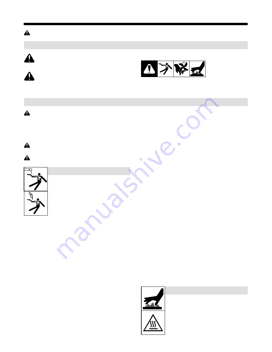
This group of symbols means Warning! Watch Out! ELECTRIC
SHOCK, MOVING PARTS, and HOT PARTS hazards. Consult sym-
bols and related instructions below for necessary actions to avoid the
hazards.

1-2.

Arc Welding Hazards

The symbols shown below are used throughout this manual
to call attention to and identify possible hazards. When you
see the symbol, watch out, and follow the related instructions
to avoid the hazard. The safety information given below is
only a summary of the more complete safety information
found in the Safety Standards listed in Section 1-5. Read and
follow all Safety Standards.

Only qualified persons should install, operate, maintain, and
repair this unit.

During operation, keep everybody, especially children, away.

Touching live electrical parts can cause fatal shocks
or  severe burns. The electrode and work circuit is
electrically live whenever the output is on. The input
power circuit and machine internal circuits are also
live when power is on. In semiautomatic or automatic
wire welding, the wire, wire reel, drive roll housing,
and all metal parts touching the welding wire are
electrically live. Incorrectly installed or improperly
grounded equipment is a hazard.

D

Do not touch live electrical parts.

ELECTRIC SHOCK can kill.

D

Wear dry, hole-free insulating gloves and body protection.

D

Insulate yourself from work and ground using dry insulating mats
or covers big enough to prevent any physical contact with the work
or ground.

D

Do not use AC output in damp areas, if movement is confined, or if
there is a danger of falling.

D

Use AC output ONLY if required for the welding process.

D

If AC output is required, use remote output control if present on
unit.

D

Additional safety precautions are required when any of the follow-
ing electrically hazardous conditions are present: in damp
locations or while wearing wet clothing; on metal structures such
as floors, gratings, or scaffolds; when in cramped positions such
as sitting, kneeling, or lying; or when there is a high risk of unavoid-
able or accidental contact with the workpiece or ground. For these
conditions, use the following equipment in order presented: 1) a
semiautomatic DC constant voltage (wire) welder, 2) a DC manual
(stick) welder, or 3) an AC welder with reduced open-circuit volt-
age. In most situations, use of a DC, constant voltage wire welder
is recommended. And, do not work alone!

D

Disconnect input power or stop engine before installing or
servicing this equipment. Lockout/tagout input power according to
OSHA 29 CFR 1910.147 (see Safety Standards).

D

Properly install, ground, and operate this equipment according to
its Owner’s Manual and national, state, and local codes.

D

Always verify the supply ground − check and be sure that input
power cord ground wire is properly connected to ground terminal in

disconnect box or that cord plug is connected to a properly
grounded receptacle outlet.

D

When making input connections, attach proper grounding conduc-
tor first − double-check connections.

D

Keep cords dry, free of oil and grease, and protected from hot metal
and sparks.

D

Frequently inspect input power cord and ground conductor for
damage or bare wiring – replace immediately if damaged – bare
wiring can kill.

D

Turn off all equipment when not in use.

D

Do not use worn, damaged, undersized, or repaired cables.

D

Do not drape cables over your body.

D

If earth grounding of the workpiece is required, ground it directly
with a separate cable.

D

Do not touch electrode if you are in contact with the work, ground,
or another electrode from a different machine.

D

Do not touch electrode holders connected to two welding ma-
chines at the same time since double open-circuit voltage will be
present.

D

Use only well-maintained equipment. Repair or replace damaged
parts at once. Maintain unit according to manual.

D

Wear a safety harness if working above floor level.

D

Keep all panels and covers securely in place.

D

Clamp work cable with good metal-to-metal contact to workpiece
or worktable as near the weld as practical.

D

Insulate work clamp when not connected to workpiece to prevent
contact with any metal object.

D

Do not connect more than one electrode or work cable to any
single weld output terminal. Disconnect cable for process not in
use.

D

Use GFCI protection when operating auxiliary equipment in damp
or wet locations.

SIGNIFICANT DC VOLTAGE exists in inverter weld-
ing power sources AFTER removal of input power.

D

Turn Off inverter, disconnect input power, and discharge input
capacitors according to instructions in Maintenance Section
before touching any parts.

HOT PARTS can burn.

D

Do not touch hot parts bare handed.

D

Allow cooling period before working on equip-
ment.

D

To handle hot parts, use proper tools and/or
wear heavy, insulated welding gloves and
clothing to prevent burns.

Summary of Contents for XMT 425 CC/CV

Page 1: ...Arc Welding Power Source XMT 425 CC CV OM 257 486D 2015 07 Processes Description Multiprocess Welding File MULTIPROCESS Visit our website at www MillerWelds com Auto Line CE R...

Page 2: ...ucts Please take time to read the Safety precautions They will help you protect yourself against potential hazards on the worksite We ve made installation and operation quick and easy With Miller you...

Page 3: ...Cycle And Overheating 10 3 6 Volt Ampere Curves 11 SECTION 4 INSTALLATION 12 4 1 Selecting A Location 12 4 2 Selecting Cable Sizes 13 4 3 Weld Output Terminals 13 4 4 Remote 14 Receptacle Information...

Page 4: ...LINE CE 907557002 Council Directives 2006 95 EC Low Voltage 2004 108 EC Electromagnetic Compatibility 2011 65 EU Restriction of the use of certain hazardous substances in electrical and electronic equ...

Page 5: ...neeling or lying or when there is a high risk of unavoid able or accidental contact with the workpiece or ground For these conditions use the following equipment in order presented 1 a semiautomaticDC...

Page 6: ...ared according to AWS F4 1 and AWS A6 0 see Safety Standards D Do not weld where the atmosphere may contain flammable dust gas or liquid vapors such as gasoline D Connect work cable to the work as clo...

Page 7: ...NG PARTS can injure D Keep away from moving parts such as fans D Keep all doors panels covers and guards closed and securely in place D Have only qualified persons remove doors panels covers or guards...

Page 8: ...NFPA Standard 51B from National Fire Protection Association Quincy MA 02269 phone 1 800 344 3555 website www nfpa org OSHA Occupational Safety and Health Standards for General Indus try Title 29 Code...

Page 9: ...rself from work and ground Safe3 2012 05 Disconnect input plug or power before working on machine Safe5 2012 05 Keep your head out of the fumes Safe6 2012 05 Use forced ventilation or local exhaust to...

Page 10: ...tributor for further information Safe37 2012 05 Disconnect input plug or power before working on machine Safe30 2012 05 Wear hat and safety glasses Use ear protection and button shirt collar Use weldi...

Page 11: ...tion Three Phase Static Frequency Converter Transformer Rectifier X Duty Cycle Percent Three Phase Panel Lift Arc Operation GTAW Remote Negative Inductance Foot Control Gas Metal Arc Welding GMAW U2 C...

Page 12: ...ge in CC Mode Max Open Circuit Voltage RMS Amps Input at Rated Load Output 60 Hz 3 Phase at NEMA Load Voltages and Class I Rating KVA KW 230 V 380 V 400 V 460 V 3 Phase 350 A at 34 VDC 60 Duty Cycle 1...

Page 13: ...ed at 0 5 meter S At a distance of 1 meter the EMF exposure values were less than 20 of the permissible values ce emf 1 2010 10 C Information On Electromagnetic Compatibility EMC This Class A equipmen...

Page 14: ...d load without overheating If unit overheats output stops a Help message is displayed and cooling fan runs Wait fifteen min utes for unit to cool Reduce amper age or voltage or duty cycle before weldi...

Page 15: ...output capabilities of welding power source Curves of other set tings fall between curves shown 0 10 20 30 40 50 60 70 80 90 100 0 100 200 300 400 500 50 75 100 25 0 AMPERAGE VOLTS A CC Mode GTAW MAX...

Page 16: ...Forks Extend forks beyond opposite side of unit 2 Lifting Handles Use handles to lift unit 3 Hand Cart Use cart or similar device to move unit 4 Line Disconnect Device Locate unit near correct input p...

Page 17: ...2x70 2x2 0 300 50 1 60 1 0 70 2 0 95 3 0 120 4 0 2x70 2x2 0 2x95 2x3 0 2x95 2x3 0 350 60 1 0 70 2 0 95 3 0 120 4 0 2x70 2x2 0 2x95 2x3 0 2x95 2x3 0 2x120 2x4 0 400 60 1 0 70 2 0 95 3 0 120 4 0 2x70 2x...

Page 18: ...DC in MIG mode D Remote control circuit common E 0 to 10 volts DC input command signal from remote control M CC CV select A V AMPERAGE VOLTAGE F Current feedback 1 volt DC per 100 weld am peres H Volt...

Page 19: ...In fitting Connect hose coupler to torch Connect one end of gas hose to hose coupler Connect remaining end of gas hose to Gas Out fitting Operation The gas solenoid controls gas flow during the TIG pr...

Page 20: ...0 11 and 630 12 60 Hz Three Phase Input Voltage V 230 380 400 460 Input Amperes A At Rated Output 36 1 22 3 20 6 17 8 Max Recommended Standard Fuse Rating In Amperes 1 Time Delay 2 40 25 25 20 Normal...

Page 21: ...OM 257 486 Page 17 Notes...

Page 22: ...OM 257 486 Page 18 4 8 Connecting 3 Phase Input Power input2 2012 05 Ref 803 766 C 803 879 B GND PE Earth Ground L1 2 1 L2 L3 3 3 4 5 6 7 Tools Needed...

Page 23: ...k the power source See rating label on unit and check input volt age available at site For Three Phase Operation 1 Input Power Cord 2 Disconnect Device switch shown in the OFF position 3 Green Or Gree...

Page 24: ...um available on remote In ELECTRODE HOT STICK mode the remote control is not used In the MIG mode remote control provides full range of unit output regardless of V A Adjust control setting 7 Arc Contr...

Page 25: ...24 5 85 Stick Actual Volts OCV Preset Amps V A 71 7 85 Actual Volts Actual Amps V A 24 5 85 V Sense Feeder Flashes OCV And Preset Blank V A 71 7 Actual Volts Actual Amps V A 24 5 250 5 3 Mode Switch S...

Page 26: ...h 2 Ref S 156 279 control 5 5 Stick Start Procedure With Stick selected start arc as fol lows 1 Electrode 2 Workpiece 3 Arc Drag electrode across workpiece like striking a match lift electrode slightl...

Page 27: ...e Damaged Or Unreadable Labels Replace Cracked Torch Body Repair Or Replace Cracked Cables Repair Or Replace Cracked Cables And Cords Clean And Tighten Weld Connections 6 Months Blow Out Inside 6 2 Bl...

Page 28: ...voltage is too low the output power is limited by the input current When this limit is reached the unit automatically reduces out put power to continue operation If this display is shown have a qualif...

Page 29: ...OM 257 486 Page 25 Notes...

Page 30: ...OM 257 486 Page 26 SECTION 7 ELECTRICAL DIAGRAM Figure 7 1 Circuit Diagram...

Page 31: ...OM 257 486 Page 27 956142946 C...

Page 32: ...76 8 11 12 13 10 74 14 83 15 16 77 19 20 17 18 75 21 22 23 24 25 28 26 38 30 31 32 29 35 34 37 36 2 82 81 78 40 39 52 55 53 54 49 17 47 45 MOD 2 MOD 1 49 48 46 50 51 79 41 42 43 44 80 57 58 56 59 60 6...

Page 33: ...nel Hole 312 Sq 500 High 4 24 PC1 265280 Circuit Card Assy Control W Program 1 216113 Stand Off Support PC Card 187 Dia W P l 375 2 PLG1 115091 Housing Plug Pins Service Kit RC1 1 PLG2 201665 Housing...

Page 34: ...Can CE Wordless 1 56 212074 Bus Bar Output 1 57 HD1 182918 Transducer Current 400A Module Supply V 15V 1 58 PC3 243654 Circuit Card Assy Front Panel Display W Program 1 PLG18 131204 Housing Plug Pins...

Page 35: ...r Polyp Film 001 Uf 2000V W Terms 1 77 L6 131447 Core Toroidal 1 332 Id X 1 932 Od X 625 Thk 1 78 L5 L7 199122 Core Toroidal 750 Id X 1 450 Od X 544 Thk 2 79 083147 Grommet Scr No 8 10 Panel Hole 312...

Page 36: ...Notes...

Page 37: ......

Page 38: ...Notes...

Page 39: ...ntrollers Powered Air Purifying Respirator PAPR Blower Unit No Labor Racks Running Gear and Trailers Subarc Wire Drive Assemblies Water Coolant Systems Work Stations Weld Tables No Labor 5 6 Months Pa...

Page 40: ...y Zip Postal Code Please complete and retain with your personal records Owner s Record Always provide Model Name and Serial Style Number Contact a DISTRIBUTOR or SERVICE AGENCY near you Welding Suppli...

Reviews: