


OM-180 231 Page 1
SECTION 1 − SAFETY PRECAUTIONS - READ BEFORE USING
coolers 2013-10
7
Protect yourself and others from injury —
read, follow, and save these important safety precautions and operating instructions.
1-1.
Symbol Usage
DANGER! − Indicates a hazardous situation which, if
not avoided, will result in death or serious injury. The
possible hazards are shown in the adjoining symbols
or explained in the text.
Indicates a hazardous situation which, if not avoided,
could result in death or serious injury. The possible
hazards are shown in the adjoining symbols or ex-
plained in the text.
NOTICE − Indicates statements not related to personal injury.
Indicates special instructions.
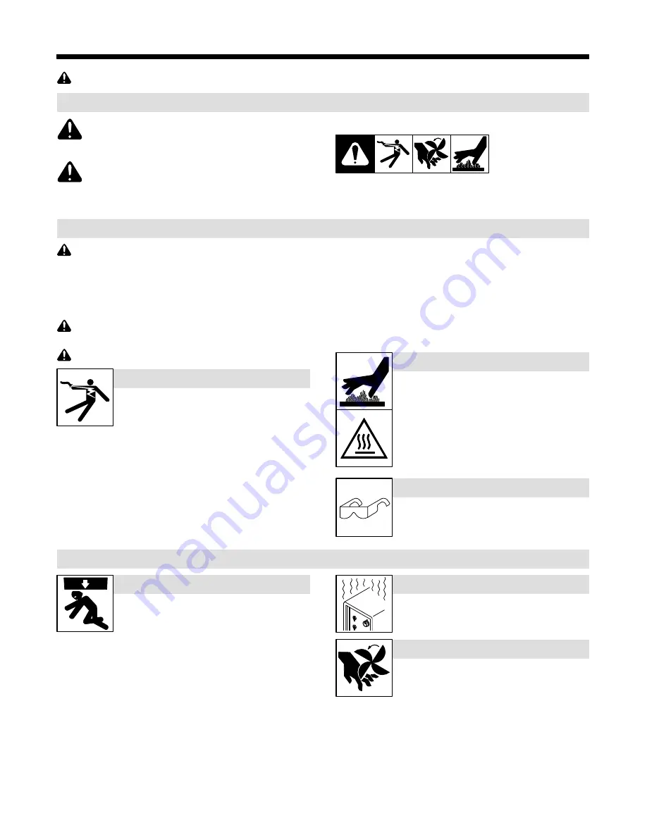
This group of symbols means Warning! Watch Out! ELECTRIC
SHOCK, MOVING PARTS, and HOT PARTS hazards. Consult sym-
bols and related instructions below for necessary actions to avoid the
hazards.
1-2.
Cooling Equipment Hazards
The symbols shown below are used throughout this manual
to call attention to and identify possible hazards. When you
see the symbol, watch out, and follow the related instructions
to avoid the hazard. The safety information given below is
only a summary of the more complete safety information
found in the Safety Standards listed in Section 1-5. Read and
follow all Safety Standards.
Only qualified persons should install, operate, maintain, and
repair this unit.
During operation, keep everybody, especially children, away.
Touching live electrical parts can cause fatal shocks
or severe burns. The input power circuit and machine
internal circuits are also live when power is on.
Incorrectly installed or improperly grounded equip-
ment is a hazard.
ELECTRIC SHOCK can kill.
Do not touch live electrical parts.
Disconnect input power or stop engine before installing or
servicing this equipment. Lockout/tagout input power according to
OSHA 29 CFR 1910.147 (see Safety Standards).
Properly install, ground, and operate this equipment according to
its Owner’s Manual and national, state, and local codes.
Always verify the supply ground − check and be sure that input
power cord ground wire is properly connected to ground terminal in
disconnect box or that cord plug is connected to a properly
grounded receptacle outlet.
Keep cords dry, free of oil and grease, and protected from hot metal
and sparks.
Frequently inspect input power cord and ground conductor for
damage or bare wiring – replace immediately if damaged – bare
wiring can kill.
Turn off all equipment when not in use.
Use only well-maintained equipment. Repair or replace damaged
parts at once. Maintain unit according to manual.
Keep all panels and covers securely in place.
HOT PARTS can burn.
Do not touch hot parts bare handed.
Allow cooling period before working on equip-
ment.
To handle hot parts, use proper tools and/or
wear heavy, insulated welding gloves and
clothing to prevent burns.
HOT PARTS can burn.
Do not touch hot parts bare handed.
Allow cooling period before working on equip-
ment.
To handle hot parts, use proper tools and/or
wear heavy, insulated welding gloves and
clothing to prevent burns.
FLYING METAL or DIRT can injure eyes.
Wear approved safety glasses with side
shields even under your welding helmet.
1-3.
Additional Symbols For Installation, Operation, And Maintenance
FALLING EQUIPMENT can injure.
Use equipment of adequate capacity to lift and
support unit.
If using lift forks to move unit, be sure forks are
long enough to extend beyond opposite side of
unit.
Keep equipment (cables and cords) away from moving vehicles
when working from an aerial location.
Follow the guidelines in the Applications Manual for the Revised
NIOSH Lifting Equation (Publication No. 94−110) when manu-
ally lifting heavy parts or equipment.
OVERUSE can cause OVERHEATING
Allow cooling period; follow rated duty cycle.
Do not block or filter airflow to unit.
MOVING PARTS can injure.
Keep away from moving parts such as fans.
Keep all doors, panels, covers, and guards
closed and securely in place.
Have only qualified persons remove doors, panels, covers, or
guards for maintenance and troubleshooting as necessary.
Reinstall doors, panels, covers, or guards when maintenance is
finished and before reconnecting input power.
Summary of Contents for PU 301
Page 4: ......
Page 11: ...OM 180 231 Page 7 Notes...
Page 14: ...TM 216 869 Page 10 Dynasty 350 700 Maxstar 350 700 Notes...
Page 15: ...Notes...