Miller PipeWorx Owner'S Manual Download Page 5

OM-239 982 Page 1

SECTION 1 

 SAFETY PRECAUTIONS - READ BEFORE USING

som 2013

09

7

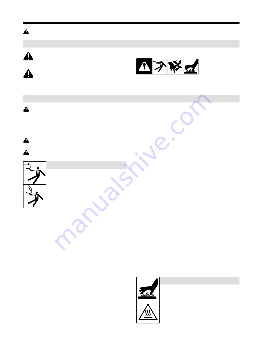
Protect yourself and others from injury —


read, follow, and save these important safety precautions and operating instructions.

1-1. Symbol Usage

DANGER! 

 Indicates a hazardous situation which, if

not avoided, will result in death or serious injury. The

possible hazards are shown in the adjoining symbols

or explained in the text.
Indicates a hazardous situation which, if not avoided,

could result in death or serious injury. The possible

hazards are shown in the adjoining symbols or ex-

plained in the text.

NOTICE


 Indicates statements not related to personal injury.

.

Indicates special instructions.

This group of symbols means Warning! Watch Out! ELECTRIC

SHOCK, MOVING PARTS, and HOT PARTS hazards. Consult sym-

bols and related instructions below for necessary actions to avoid the

hazards.

1-2. Arc Welding Hazards

The symbols shown below are used throughout this manual

to call attention to and identify possible hazards. When you

see the symbol, watch out, and follow the related instructions

to avoid the hazard. The safety information given below is

only a summary of the more complete safety information

found in the Safety Standards listed in Section 1-5. Read and

follow all Safety Standards.

Only qualified persons should install, operate, maintain, and

repair this unit.

During operation, keep everybody, especially children, away.

Touching live electrical parts can cause fatal shocks

or  severe burns. The electrode and work circuit is

electrically live whenever the output is on. The input

power circuit and machine internal circuits are also

live when power is on. In semiautomatic or automatic

wire welding, the wire, wire reel, drive roll housing,

and all metal parts touching the welding wire are

electrically live. Incorrectly installed or improperly

grounded equipment is a hazard.

D

Do not touch live electrical parts.

ELECTRIC SHOCK can kill.

D

Wear dry, hole-free insulating gloves and body protection.

D

Insulate yourself from work and ground using dry insulating mats

or covers big enough to prevent any physical contact with the work

or ground.

D

Do not use AC output in damp areas, if movement is confined, or if

there is a danger of falling.

D

Use AC output ONLY if required for the welding process.

D

If AC output is required, use remote output control if present on

unit.

D

Additional safety precautions are required when any of the follow-

ing electrically hazardous conditions are present: in damp

locations or while wearing wet clothing; on metal structures such

as floors, gratings, or scaffolds; when in cramped positions such

as sitting, kneeling, or lying; or when there is a high risk of unavoid-

able or accidental contact with the workpiece or ground. For these

conditions, use the following equipment in order presented: 1) a

semiautomatic DC constant voltage (wire) welder, 2) a DC manual

(stick) welder, or 3) an AC welder with reduced open-circuit volt-

age. In most situations, use of a DC, constant voltage wire welder

is recommended. And, do not work alone!

D

Disconnect input power or stop engine before installing or

servicing this equipment. Lockout/tagout input power according to

OSHA 29 CFR 1910.147 (see Safety Standards).

D

Properly install, ground, and operate this equipment according to

its Owner’s Manual and national, state, and local codes.

D

Always verify the supply ground 

 check and be sure that input

power cord ground wire is properly connected to ground terminal in

disconnect box or that cord plug is connected to a properly

grounded receptacle outlet.

D

When making input connections, attach proper grounding conduc-

tor first 

 double-check connections.

D

Keep cords dry, free of oil and grease, and protected from hot metal

and sparks.

D

Frequently inspect input power cord and ground conductor for

damage or bare wiring – replace immediately if damaged – bare

wiring can kill.

D

Turn off all equipment when not in use.

D

Do not use worn, damaged, undersized, or repaired cables.

D

Do not drape cables over your body.

D

If earth grounding of the workpiece is required, ground it directly

with a separate cable.

D

Do not touch electrode if you are in contact with the work, ground,

or another electrode from a different machine.

D

Do not touch electrode holders connected to two welding ma-

chines at the same time since double open-circuit voltage will be

present.

D

Use only well-maintained equipment. Repair or replace damaged

parts at once. Maintain unit according to manual.

D

Wear a safety harness if working above floor level.

D

Keep all panels and covers securely in place.

D

Clamp work cable with good metal-to-metal contact to workpiece

or worktable as near the weld as practical.

D

Insulate work clamp when not connected to workpiece to prevent

contact with any metal object.

D

Do not connect more than one electrode or work cable to any

single weld output terminal. Disconnect cable for process not in

use.

D

Use GFCI protection when operating auxiliary equipment in damp

or wet locations.

SIGNIFICANT DC VOLTAGE exists in inverter weld-

ing power sources AFTER removal of input power.

D

Turn Off inverter, disconnect input power, and discharge input

capacitors according to instructions in Maintenance Section

before touching any parts.

HOT PARTS can burn.

D

Do not touch hot parts bare handed.

D

Allow cooling period before working on equip-

ment.

D

To handle hot parts, use proper tools and/or

wear heavy, insulated welding gloves and

clothing to prevent burns.

Summary of Contents for PipeWorx

Page 1: ...982B 2014 03 Processes MIG GMAW and Pulsed MIG GMAW P Welding Description PipeWorx Remote Feeder Interface w Cable File MIG GMAW Visit our website at www MillerWelds com Flux Cored FCAW Welding Wire...

Page 2: ...ntinue the tradition They re just as committed to providing equipment and service that meets the high standards of quality and value established in 1929 This Owner s Manual is designed to help you get...

Page 3: ...nts 9 2 5 Principales normes de s curit 9 2 6 Informations relatives aux CEM 9 SECTION 3 INSTALLATION 11 3 1 Specifications 11 3 2 System Connections 11 3 3 Remote Interface Cable Connector PLG6 Infor...

Page 4: ......

Page 5: ...neeling or lying or when there is a high risk of unavoid able or accidental contact with the workpiece or ground For these conditions use the following equipment in order presented 1 a semiautomaticDC...

Page 6: ...ared according to AWS F4 1 and AWS A6 0 see Safety Standards D Do not weld where the atmosphere may contain flammable dust gas or liquid vapors such as gasoline D Connect work cable to the work as clo...

Page 7: ...NG PARTS can injure D Keep away from moving parts such as fans D Keep all doors panels covers and guards closed and securely in place D Have only qualified persons remove doors panels covers or guards...

Page 8: ...NFPA Standard 51B from National Fire Protection Association Quincy MA 02269 phone 1 800 344 3555 website www nfpa org OSHA Occupational Safety and Health Standards for General Indus try Title 29 Code...

Page 9: ...UNIQUE MENT si le proc d de soudage le demande D Si l utilisation d une source lectrique courant lectrique s av re n cessaire se servir de la fonction de t l commande si l appareil en est quip D D aut...

Page 10: ...nts et les tincelles pr venir toute personne sur les lieux de ne pas regarder l arc D Porter un quipement de protection pour le corps fait d un mat riau r sistant et ignifuge cuir coton robuste laine...

Page 11: ...ci s en bon tat D Tourner le dos la sortie de vanne lors de l ouverture de la vanne de la bouteille Ne pas se tenir devant ou derri re le r gulateur lors de l ouverture de la vanne D Le couvercle du d...

Page 12: ...es de rechange recommand es par le constructeur D Effectuer l entretien en respectant les manuels d utilisation les normes industrielles et les codes nationaux d tat et locaux LE RAYONNEMENT HAUTE FR...

Page 13: ...l Fire Protection Association Quincy MA 02269 phone 1 800 344 3555 website www nfpa org OSHA Occupational Safety and Health Standards for General Indus try Title 29 Code of Federal Regulations CFR Par...

Page 14: ...OM 239 982 Page 10...

Page 15: ...ht 11 1 4 in 286 mm 5 1 2 lb 2 4 kg 3 2 System Connections 245 255 A Turn Off welding power source and disconnect input power 1 PipeWorx System 2 PipeWorx Feeder Remote 3 Remote Interconnect Cable Whe...

Page 16: ...G6 Socket Socket Information 24 Volts AC Input C 24 volts AC F 24 volts AC return Connected to chassis common Completes 24 volts AC power supply circuit to remote interface Serial Communication A Isol...

Page 17: ...G3 6 Cable Remote Pendant Connector PLG4 Align connector keyways with receptacles insert plugs and tighten locking rings Left trigger connector should mate with left trigger receptacle and right trigg...

Page 18: ...Closure with pin 2 activates right trigger 2 Closure with pin 1 activates right trigger Sockets 3 and 4 are not used 3 6 Remote Interface Cable Connector PLG4 Information Plug PLG4 Socket Socket Infor...

Page 19: ...splay 3 Volts Arc Length Adjust Knob 4 Right Side Controls Select Button 5 Wire Feed Speed Display 6 Wire Feed Speed Adjust Knob 7 Memory Card Indicator 8 MIG Process Type Indicator 9 Jog Button 10 Tr...

Page 20: ...0 to 3 0 in 0 1 increments with 0 as nominal depending on the type of MIG process selection Rotating the knob clockwise increases volts arc length and counter clockwise decreases volts arc length Volt...

Page 21: ...e volts arc length display will show the set wire length for a short time after making any desired adjustment If no further changes are made to the wire length after one second the unit will resume th...

Page 22: ...der 14 Right Trigger Switch When the right side trigger connector from the remote cable is connected to the front of the feeder turn this switch on to activate the right side feeder Turn off switch to...

Page 23: ...Side Active Setup Example When Using Right Side Trigger 4 1 2 3 Only illuminated controls can be changed or adjusted 1 Right Side Controls Active 2 Pulse Process Selected 3 Trigger Hold On 4 Memory Lo...

Page 24: ...SECTION 5 MAINTENANCE AND TROUBLESHOOTING Disconnect power before maintaining 5 1 Routine Maintenance n Check Clean l Replace Every 3 Months l Unreadable Labels nl Cords nl Cracked Parts Every 6 Mont...

Page 25: ...e Agent H11 Primary Bus Capacitor Voltage Imbalance Indicates primary power circuit is malfunctioning If this code appears on the display contact the nearest Factory Authorized Service Agent H12 Prima...

Page 26: ...ysical switch on the memory card Unlock the memory card and try again Try a different memory card Remove card or press any button to clear error If this code continues to ap pear on the display contac...

Page 27: ...OM 239 982 Page 23 Notes...

Page 28: ...OM 239 982 Page 24 SECTION 6 ELECTRICAL DIAGRAM Figure 6 1 Circuit Diagram For Remote Feeder Interface...

Page 29: ...OM 239 982 Page 25 239 983 A...

Page 30: ...OM 239 982 Page 26 SECTION 7 PARTS LIST Hardware is common and not available unless listed 245 259 A 1 2 3 4 5 6 8 7 9 10 11 7 12 13 Figure 7 1 Main Assembly...

Page 31: ...111997 Switch Rocker Spst 10A 250VAC On Off VISI Red Rock 2 6 244067 Sheild Bezel 1 7 239978 Handle Round Wire 2 8 244064 Case 1 9 239981 Eye Bolt 250 20 x 1 00 1 10 244160 Circuit Card Assy Filter 1...

Page 32: ...Notes...

Page 33: ...Notes...

Page 34: ...Notes...

Page 35: ...Warranty shall not apply to 1 Consumable components such as contact tips cutting nozzles contactors brushes relays work station table tops and welding curtains or parts that fail due to normal wear Ex...

Page 36: ...your personal records Always provide Model Name and Serial Style Number Contact a DISTRIBUTOR or SERVICE AGENCY near you Welding Supplies and Consumables Options and Accessories Personal Safety Equip...

Reviews: