© Miller Diving All Rights Reserved Document # 030715001
17
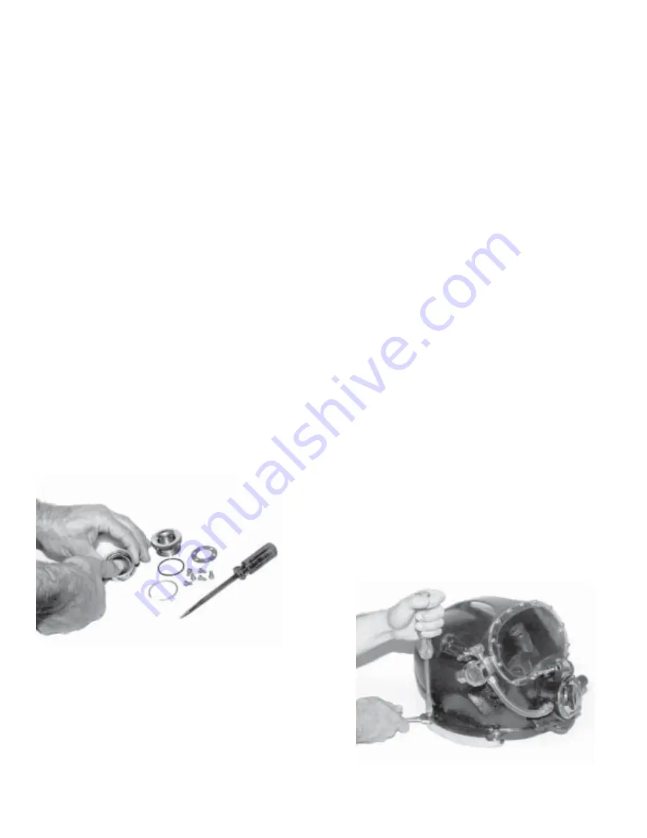
Adjust Cams with a wrench and screwdriver.
Press Rubber Exhaust Valve firmly into place with
thumb. Be sure tip exits on opposite side.
3. The O-ring may be removed with a blunt screwdriver,
being careful not to damage the inner surface of the Ex-
haust Body.
4. To remove brass Exhaust Body, unscrew the six Screws
from inside the Helmet. Remove the Exhaust Retainer
Plate. Push the body out from the inside.
5. Before replacing the Exhaust Body, clean any old sili-
cone sealant from Helmet and Exhaust body.
6. Replace Body O-ring and coat base of Exhaust Body
including O-ring with silicone sealant.
7. Place Exhaust Body in hole, making sure Ports are fac-
ing up and back.
8. Replace Exhaust Retainer Plate and fasten with the six
Screws inside the Helmet. (Be certain that the O-ring has
not popped out from its groove).
9. Excess silicone sealant should be removed by letting it
cure for about 20 minutes, then run a toothpick around
edge and peel it off.
10. Lightly lubricate new inner O-ring with silicone grease
and install.
11. Lightly lubricate the tip of Rubber Exhaust Valve with
silicone grease. Insert tip in hole and press firmly into place
with thumb. (Be sure the tip exits on opposite side of Ex-
haust Body to lock in place).
3-I
CAMS
DESCRIPTION:
The two Cam Handles lock the Neck Ring tight against
the Neoprene Gasket with four points, for an effective
water tight seal. The Cams are simple, rugged and de-
signed for quick, jam-proof operation. They are easily
adjusted with the Handle Screw and Cam Nuts.
MAINTENANCE AND REPLACEMENT
1. To remove handle, loosen Cam Lock Nut and unscrew
the Handle Screw at the rear Helmet ear and remove the
Cam.
2. To replace Cam Handle, install Cam on rear Helmet
ear in this order:
3. Place Screw through ear, from top down.
4. Position Washers, usually three, under rear ear.
5. Install Cam Nut under Washers (not tight).
6. Place Cam on bottom and fasten with Screw until snug.
7. Tighten Cam Nut against Cam. The Screw, Cam Nut,
and Cam are now locked together. The Cam Handle should
swivel freely, without up and down play, on the rear Hel-
met ear.
8. The front ear tension adjusts with Screw and Lock Nut.
NOTE: The amount of washers determines the amount of
tension on rear ear, to lock the Neck Ring in place. Three
Washers are normally used in both front and rear ear.
Proper tension is achieved when pressure is sufficient to
press Neck Ring into the Gasket and Dam approximately
1/16 of an inch.
12. Place Split Clip Ring on Handle between threads and
top.
13. Screw the Handle into the Exhaust Body, allowing 1/4
in. space between the Body and Handle top. Clip Ring
may now be forced into the retaining groove in Exhaust
Body using a blunt screwdriver. (The purpose of clip ring
is to prevent the handle from unscrewing all the way out
of the Exhaust Body).


