background image

OM-206 

3

60 Page 2

Arc rays from the welding process produce intense

visible and invisible (ultraviolet and infrared) rays

that can burn eyes and skin. Sparks fly off from the

weld.

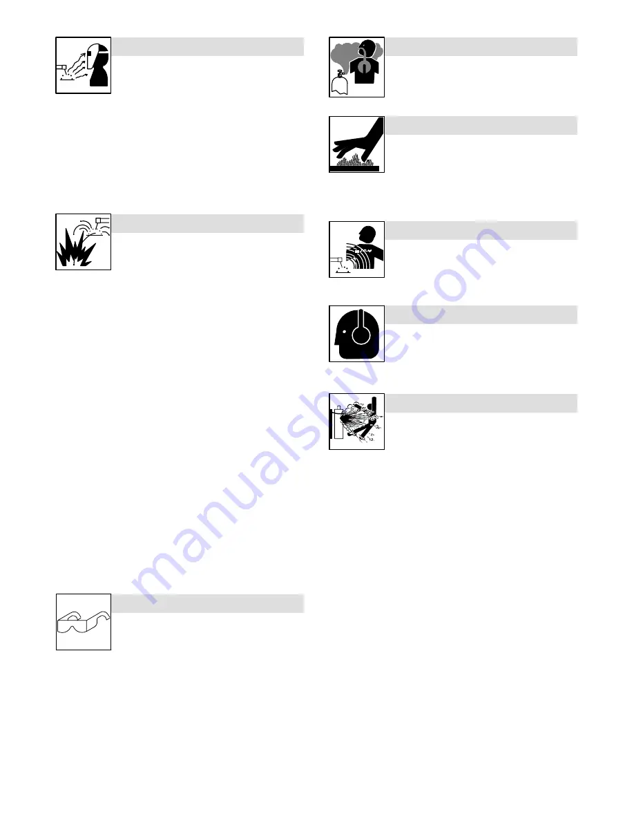
ARC RAYS can burn eyes and skin.

D

Wear an approved  welding helmet fitted with a proper shade of fil-

ter lenses to protect your face and eyes when welding or watching

(see ANSI Z49.1 and Z87.1 listed in Safety Standards).

D

Wear approved safety glasses with side shields under your

helmet.

D

Use protective screens or barriers to protect others from flash,

glare and sparks; warn others not to watch the arc.

D

Wear protective clothing made from durable, flame-resistant mate-

rial (leather, heavy cotton, or wool) and foot protection.

Welding on closed containers, such as tanks,

drums, or pipes, can cause them to blow up. Sparks

can fly off from the welding arc. The flying sparks, hot

workpiece, and hot equipment can cause fires and

burns. Accidental contact of electrode to metal objects can cause

sparks, explosion, overheating, or fire. Check and be sure the area is

safe before doing any welding.

WELDING can cause fire or explosion.

D

Remove all flammables within 35 ft (10.7 m) of the welding arc. If

this is not possible, tightly cover them with approved covers.

D

Do not weld where flying sparks can strike flammable material.

D

Protect yourself and others from flying sparks and hot metal.

D

Be alert that welding sparks and hot materials from welding can

easily go through small cracks and openings to adjacent areas.

D

Watch for fire, and keep a fire extinguisher nearby.

D

Be aware that welding on a ceiling, floor, bulkhead, or partition can

cause fire on the hidden side.

D

Do not weld on closed containers such as tanks, drums, or pipes,

unless they are properly prepared according to AWS F4.1 (see

Safety Standards).

D

Connect work cable to the work as close to the welding area as

practical to prevent welding current from traveling long, possibly

unknown paths and causing electric shock, sparks, and fire

hazards.

D

Do not use welder to thaw frozen pipes.

D

Remove stick electrode from holder or cut off welding wire at

contact tip when not in use.

D

Wear oil-free protective garments such as leather gloves, heavy

shirt, cuffless trousers, high shoes, and a cap.

D

Remove any combustibles, such as a butane lighter or matches,

from your person before doing any welding.

D

Follow requirements in OSHA 1910.252 (a) (2) (iv) and NFPA 51B

for hot work and have a fire watcher and extinguisher nearby.

FLYING METAL can injure eyes.

D

Welding, chipping, wire brushing, and grinding

cause sparks and flying metal. As welds cool,

they can throw off slag.

D

Wear approved safety glasses with side

shields even under your welding helmet.

BUILDUP OF GAS can injure or kill.

D

Shut off shielding gas supply when not in use.

D

Always ventilate confined spaces or use

approved air-supplied respirator.

HOT PARTS can cause severe burns.

D

Do not touch hot parts bare handed.

D

Allow cooling period before working on gun or

torch.

D

To handle hot parts, use proper tools and/or

wear heavy, insulated welding gloves and

clothing to prevent burns.

MAGNETIC FIELDS

 can affect pacemakers.

D

Pacemaker wearers keep away.

D

Wearers should consult their doctor before

going near arc welding, gouging, or spot

welding operations.

NOISE can damage hearing.

Noise from some processes or equipment can

damage hearing.

D

Wear approved ear protection if noise level is

high.

Shielding gas cylinders contain gas under high

pressure. If damaged, a cylinder can explode. Since

gas cylinders are normally part of the welding

process, be sure to treat them carefully.

CYLINDERS can explode if damaged.

D

Protect compressed gas cylinders from excessive heat, mechani-

cal shocks, physical damage, slag, open flames, sparks, and arcs.

D

Install cylinders in an upright position by securing to a stationary

support or cylinder rack to prevent falling or tipping.

D

Keep cylinders away from any welding or other electrical circuits.

D

Never drape a welding torch over a gas cylinder.

D

Never allow a welding electrode to touch any cylinder.

D

Never weld on a pressurized cylinder 

 explosion will result.

D

Use only correct shielding gas cylinders, regulators, hoses, and fit-

tings designed for the specific application; maintain them and

associated parts in good condition.

D

Turn face away from valve outlet when opening cylinder valve.

D

Keep protective cap in place over valve except when cylinder is in

use or connected for use.

D

Use the right equipment, correct procedures, and sufficient num-

ber of persons to lift and move cylinders.

D

Read and follow instructions on compressed gas cylinders,

associated equipment, and Compressed Gas Association (CGA)

publication P-1 listed in Safety Standards.

Summary of Contents for INFINITY 35

Page 1: ...INFINITY 35 45 Processes OM 206360 C 2006 07 Effective with serial number 217 769 www MillerWelds com Description MIG GMAW Welding Flux Cored FCAW OWNER S MANUAL...

Page 2: ...ucts Please take time to read the Safety precautions They will help you protect yourself against potential hazards on the worksite We ve made installation and operation quick and easy With Miller you...

Page 3: ...Rating Labels For CE Products 7 2 3 Symbols And Definitions 7 2 4 Duty Cycle And Overheating 8 2 5 Volt Ampere Curves 8 2 6 Weld Output Terminals And Selecting Cable Sizes 9 SECTION 3 INSTALLATION 10...

Page 4: ...that this product INFINITY 35 45 conforms to the following Directives and Standards Directives Low Voltage 73 23 EEC Machinery Directives 89 392 EEC And their amendments 91 368 EEC 93 C 133 04 93 68 E...

Page 5: ...0 147 see Safety Standards D Properly install and ground this equipment according to its Owner s Manual and national state and local codes D Always verify the supply ground check and be sure that inpu...

Page 6: ...mbustibles such as a butane lighter or matches from your person before doing any welding D Follow requirements in OSHA 1910 252 a 2 iv and NFPA 51B for hot work and have a fire watcher and extinguishe...

Page 7: ...es computers and communicationsequipment D Have only qualified persons familiar with electronic equipment perform this installation D The user is responsible for having a qualified electrician prompt...

Page 8: ...Occupational Safety and Health Standards for General Indus try Title 29 Code of Federal Regulations CFR Part 1910 Subpart Q and Part 1926 Subpart J from U S Government Printing Office Super intendent...

Page 9: ...rks can cause explosion or fire 3 1 Keep flammables away from welding Do not weld near flammables 3 2 Welding sparks can cause fires Have a fire extinguisher nearby and have a watchperson ready to use...

Page 10: ...4 Having a loop of extra length connect grounding conductor first 5 Connect line input conductors as shown on inside label double check all connections jumper link positions and input voltage before...

Page 11: ...Definitions Some symbols are found only on CE products NOTE A Amperes Amperage Voltage Control Panel Gas Tungsten Arc Welding GTAW Shielded Metal Arc Welding SMAW Temperature Wire Feeder Arc Force DI...

Page 12: ...r duty cycle before welding Y Exceeding duty cycle can damage unit and void warranty 100 Duty Cycle Overheating 0 15 A V OR Reduce Duty Cycle Minutes duty1 4 95 Ref SA 168 918 Continuous Welding 20 25...

Page 13: ...Copper Length In Weld Circuit Not Exceeding 100 ft 30 m Or Less 150 ft 45 m 200 ft 60 m 250 ft 70 m 300 ft 90 m 350 ft 105 m 400 ft 120 m Welding Amperes 10 60 Duty Cycle 60 100 Duty Cycle 10 100 Duty...

Page 14: ...N 3 1 Selecting A Location 1 Lifting Eye 2 Lifting Forks Use lifting eye or lifting forks to move unit If using lifting forks extend forks beyond opposite side of unit OR 1 2 Movement Position unit so...

Page 15: ...ain to running gear 5 Cylinder valve Open valve slightly so gas flow blows dirt from valve Close valve 6 Regulator Flow gauge Install so face is vertical 7 Flow adjust 8 Gas supply line 9 Wire feeder...

Page 16: ...1 3 5 Electrical Service Guide Infinity 35 Infinity 45 Input Voltage 230 400 230 400 Input amperes at rated output 36A 21A 52A 30A Fuse or circuit breaker rating max rec 36A 21A 51A 29A Input conduct...

Page 17: ...reg ulations GND PE Connect first GND PE L1 L2 L3 115 VAC Single phase 50 Hz 10 A 3 7 Controls 1 115 a c Receptacle Located on the rear panel is a re ceptacle which provides power to the gas heater w...

Page 18: ...ON OFF 4 Circuit breaker This circuit protects the auxiliary power 5 High inductance negative out put terminal Connect work lead here for stain less steel and spray arc conditions 6 Low inductance ne...

Page 19: ...link position Clean and tighten all weld output connections Unit provides only maximum or minimum weld output Have Factory Authorized Service Agent check control board PC1 and hall device HD1 Erratic...

Page 20: ...OM 206 360 Page 16 Notes...

Page 21: ...30 Marrone Grigio 25 4 41 42 70 71 40 57 R PRI TP2 TP3 56 54 55 53 Cr1 380V 220V C1 S C2 C3 T TP5 TP4 CR1 in transf in rect TP6 49 48 41 Viola Giallo 6 1 2 4 5 3 14 7 13 6 4 11 5 12 2 9 3 10 1 8 6 3 2...

Page 22: ...6 360 Page 18 SECTION 6 PARTS LIST 6 1 Main Assembly Infinity 35 45 32 36 23 17 33 30 31 1 40 41 13 35 39 38 37 44 42 13 34 14 45 4 5 6 7 8 9 11 12 16 18 19 24 46 15 10 3 26 47 27 21 22 48 28 29 20 25...

Page 23: ...SR1 028018067 XK 2 1 18 SR1 028018063 XH 2 1 19 SR 2 028018062 XH 3 1 1 20 028038050 XK 5 1 20 028038049 XH 11 1 21 756069012 BO 0 0 6 1 1 22 556070011 HD 0 0 2 3 3 23 156006030 XH 0 0 6 1 1 26 230 40...

Page 24: ...Notes...

Page 25: ...Notes...

Page 26: ...Notes...

Page 27: ...shall not apply to 1 Consumable components such as contact tips cutting nozzles contactors brushes slip rings relays or parts that fail due to normal wear 2 Items furnished by Miller but manufactured...

Page 28: ...stal Code Please complete and retain with your personal records Owner s Record Always provide Model Name and Serial Style Number Contact a DISTRIBUTOR or SERVICE AGENCY near you Welding Supplies and C...

Reviews: