background image

OM-222 394 Page 23

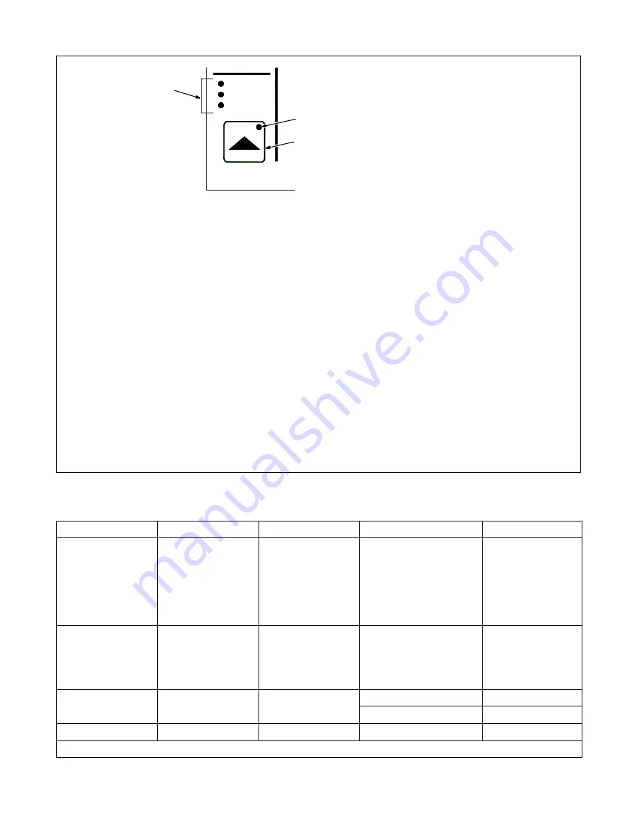
6-10. Process Set Up Push Button

Press the Process Set Up push button the

first time will illuminate the button LED and

the Process LED. The upper and lower

displays will be used for Accu-pulse and

only the lower display for MIG, Pulse and

RMD (optional) to show the current process

installed in this program. To change

process, turn the adjust knob.

Pressing the Process Set Up push button a

second time will illuminate the Wire Type

LED and the lower display will show wire

types available for selected processes (see

Table 6-1 for wire abbreviation). To make a

selection, turn the Adjust knob.

Pressing the Process Set Up push button a

third time will keep Wire Type LED lit and the

upper display will show wire alloy type (see

Table 6-1 for alloy types). The upper display

push-button LED will be flashing indicating

that turning the Adjust knob will change the

alloy type for the selected process and wire

type.

Pressing the Process Set Up push button a

fourth time will keep Wire Type LED lit and

the upper display will show wire size. The

upper display push button will be flashing

indicating that turning the Adjust knob will

select wire sizes available for that particular

process and wire type.

Pressing the Process Set Up push button a

fifth time will illuminate the Gas Type LED

and the lower display will show GAS and the

upper display will show gas selection (see

Table 6-1 for gas abbreviations). To make a

gas type selection, turn the Adjust knob.

If any of the Process, wire type, alloy type,

wire size, or gas type was changed, then

pressing the Process Set Up push button a

sixth time will show PROG in the upper

display and LOAD in the lower display. The

new program would be loaded for that

particular program in slot 1 thru 8. If no

changes were made to any setup items, no

program will be loaded, and unit will return

to standby mode.

If a custom program is loaded using an

optional PDA with File Management/Wa-

veWriter software, the Program Display will

have a “C” in front of the program number.

This indicates that the program is not a

factory default program and has been

modified. By selecting or changing any

process variable and performing a program

load will restore the program back to the

factory default program.

Pressing and holding the Process Set Up

push button in on power up allows viewing

the software revisions of each circuit board

in the system. The top display shows the

board (PCM, UIM, WFCM, and AIM (auto-

mated units only) and the lower display

shows the last 3 digits of the circuit board

part number plus a letter designator. Press

the flashing Feeder Set Up push button to

exit the screen displays and continue the

power up process.

1

3

2

1

Process Set Up Push Button

2

Process Set Up LED

3

Program Selection LEDs

Process
Wire Type

Gas Type

Process Set Up

Table 6-1. Welding Wire And Gas Abbreviations*

Wire Description

Wire Abbreviation

Alloy Type

Gas Type

Gas Abbreviation

Steel

STL

E70, E100, E120

100% CO

2

,

90% Argon/10% CO

2

,

85% Argon/15% CO

2

,

75% Argon/25% CO

2

,

95% Argon/5% CO

2

,

95% Argon /5% O

2

,

98% Argon/2% O

2

CO2

C10

C15

C25

C5

OX5

OX2

Stainless Steel

SS

308, 309, 312, 316

98% Argon, 2% O

2

(81Ar/18HE/1CO

2

Accu-pulse)

90HE/7-1/2Ar/2-1/2CO

2

MIG/RMD)

OX2

Tri Gas

Tri Gas

Cored Tubular Wire

MCOR

71, 76, 86R, 409

90% Argon/10% CO

2

C10

98% Argon/2% O

2

OX2

Aluminum

ALUM

4XXX, 5XXX

100% Argon

ARGN

* Not all wire types may be available with your unit.

Summary of Contents for 394F

Page 1: ...Wire Feeder Processes Description MIG GMAW Welding Flux Cored FCAW Welding Gas And Self Shielded Wire Feeder OM 222 394F 2006 08 File Advanced Manufacturing Systems Visit our website at www MillerWel...

Page 2: ...tinue the tradition They re just as committed to providing equipment and service that meets the high standards of quality and value established in 1929 This Owner s Manual is designed to help you get...

Page 3: ...ting A Location 9 4 2 Connection Diagram 10 4 3 Rear Panel Connections And Rotating Drive Assembly 11 4 4 9 Pin Network Receptacle Information 12 4 5 Gun Recommendation Table 12 4 6 Installing And Thr...

Page 4: ......

Page 5: ...0 147 see Safety Standards D Properly install and ground this equipment according to its Owner s Manual and national state and local codes D Always verify the supply ground check and be sure that inpu...

Page 6: ...mbustibles such as a butane lighter or matches from your person before doing any welding D Follow requirements in OSHA 1910 252 a 2 iv and NFPA 51B for hot work and have a fire watcher and extinguishe...

Page 7: ...s computers and communicationsequipment D Have only qualified persons familiar with electronic equipment perform this installation D The user is responsible for having a qualified electrician prompt l...

Page 8: ...Occupational Safety and Health Standards for General Indus try Title 29 Code of Federal Regulations CFR Part 1910 Subpart Q and Part 1926 Subpart J from U S Government Printing Office Super intendent...

Page 9: ...la norme OSHA 29 CFR 1910 147 voir normes de s curit D Installer le poste correctement et le mettre la terre convenablement selon les consignes du manuel de l op rateur et les normes nationales provi...

Page 10: ...es poches telles qu un allumeur au butane ou des allumettes D Suivre les consignes de OSHA 1910 252 a 2 iv et de NFPA 51B pour travaux de soudage et pr voir un d tecteur d incendie et un ex tincteur p...

Page 11: ...ut provoquer des interf rences avec les quipe ments de radio navigation et de communica tion les services de s curit et les ordinateurs D Demander seulement des personnes qualifi es familiaris es avec...

Page 12: ...bpart Q and Part 1926 Subpart J de U S Government Printing Office Superinten dent of Documents P O Box 371954 Pittsburgh PA 15250 il y a 10 bureaux r gionaux le t l phone de la r gion 5 Chicago est 31...

Page 13: ...m 87 lb 39 5 kg SECTION 4 INSTALLATION 4 1 Selecting A Location loc_2 3 96 804 018 A Y Do not stack units Beware of tipping 1 Lifting Forks Use lifting forks to move unit Extend forks beyond opposite...

Page 14: ...s Cylinder 4 Gas Hose 5 Network Feeder Cable 6 Negative Weld Cable 7 Workpiece 8 Voltage Sensing Lead Recommendedfor Accu pulse and RMD optional Positive voltage sensing lead is contained in the motor...

Page 15: ...Right Requires fitting with 5 8 18 right hand threads Connect customer supplied gas hose 4 Weld Cable Terminal 5 Jumper Cable 6 Weld Cable 7 Drive Assembly 8 Drive Assembly Rotation Knob Left And Rig...

Page 16: ...B Shield G F C Volt sense H G E F D Can low I H D E E Can high A B I C D F 24 volts dc common B C G 24 volts dc H Motor voltage 40 volts dc common I Motor voltage 40 volts dc 4 5 Gun Recommendation T...

Page 17: ...soft wire or small diameter stainless steel wire reduce drive roll pressure on the rear roll to half that of the front rolls To adjust drive roll pressure hold nozzle about 2 in 51 mm from nonconducti...

Page 18: ...ontrol Adjust Volts Time WFS Amps Process Set Up Feeder Set Up Trigger Hold 2 1 Power Source Upper Display Lower Display Axcess Axcs 300 450 675 10 44 Voltage Range Arc Length Arc Ctl Sequence Net Wai...

Page 19: ...by peak and minimum current levels Benefits are shorter arc lengths better puddle control more tolerant of tip to work variation less audible noise no arc wandering allows weld to fill in at toes inc...

Page 20: ...oftware Crater Allows setting of voltage arc adjust wire feed rate and time value for arc ends Postflow Setting a time value for gas flow after arc end Feeder Set Up Allow selection of Sequence and tr...

Page 21: ...Right Select Switch Pressing the Left Right Select switch allows the operator to choose which side of the units con trols will operate 6 2 Left Right Select Switch 804 022 A Depressing the Left or Rig...

Page 22: ...If the gun trigger is still activated after 30 seconds the jog operation is terminated to prevent complete unspooling of the wire and an ERR STRT message is displayed on the upper and lower displays R...

Page 23: ...See Section 6 6 See Section 6 7 See Section 6 10 See Section 6 9 See Section 6 8 See Section 6 5 Program Process Wire Type Gas Type Trigger Control Adjust Volts Time WFS Amps Process Set Up Feeder Set...

Page 24: ...s after welding stops before returning to preset value 2 Upper Display Push Button Press the button to illuminate the LED and allow changing information in the display 3 Upper Display Push Button LED...

Page 25: ...and can be adjusted using the Adjust knob 6 Lower Display Push Button 7 Lower Display Push Button LED Pressing the button illuminates the LED and selects either WFS or Arc Ctl value for changing using...

Page 26: ...ither STRT or CRTR and the WFS LED will begin flash ing Use the Adjust knob to change the WFS value Pressing the Feeder Set Up button two more times will exit the Sequence menu and return the system t...

Page 27: ...p push button a sixth time will show PROG in the upper display and LOAD in the lower display The new program would be loaded for that particular program in slot 1 thru 8 If no changes were made to any...

Page 28: ...3 Accu pulse 035 Mild Steel 90 Argon 10 O2 Program 4 Pulse 045 Mild Steel 90 Argon 10 CO2 Program 5 MIG 045 Mild Steel 75 Argon 25 CO2 Program 6 Accu pulse 045 Mild Steel 90 Argon 10 O2 Program 7 Pul...

Page 29: ...oftware If time is set to zero in any timed sequence the sequence is skipped Maximum IPM may actually be lower depending on the process and wire type selection Trigger Pressed Trigger Released Start T...

Page 30: ...Maintain more often during severe conditions n Check Z Change Clean l Replace To be done by Factory Authorized Service Agent Reference Every 3 l Unreadable Labels Weld Terminals l Damaged Gas Hose nl...

Page 31: ...g Purge button ERR GND The ground current error occurs if weld current is detected in the earth ground connection May be caused by a conductor making contact with unit chassis Check and repair feeder...

Page 32: ...emergency stop button Reset the emergency stop button and press Jog Purge button to clear error RMD DONE The RMD done error indicates the RMD demo is completed Press Jog Purge button to clear error O...

Page 33: ...wner s Manual Readjust hub tension and drive roll pressure see Section 4 6 Change to correct size drive roll see 4 6 Clean or replace dirty or worn drive roll Incorrect size or worn wire guides Replac...

Page 34: ...OM 222 394 Page 30 SECTION 9 ELECTRICAL DIAGRAM Figure 9 1 Circuit Diagram...

Page 35: ...OM 222 394 Page 31 218 564 D...

Page 36: ...94 Page 32 SECTION 10 PARTS LIST 804 023 A Hardware is common and not available unless listed 12 19 2 1 3 17 18 7 16 8 11 9 10 6 20 15 11 10 14 5 22 4 Figure 10 3 21 Figure 10 2 9 13 Figure 10 1 Main...

Page 37: ...B spool 1 13 071 730 TUBING stl 875 OD x 12 ga wall x 2 500 1 14 135 205 NUT 625 11 94 hex 77H stl pld elastic stop nut 1 15 141 411 SUPPORT spool 1 16 208 339 KNOB w extension LH clamp 1 16 208 338 K...

Page 38: ...SSY motor filter 2 10 220 063 CIRCUIT CARD ASSY relay 1 11 010 494 BUSHING snap in nyl 1 375 id x 1 750 mtg hole 2 220 314 FILTER ASSY sense lead including 2 12 038 855 BLOCK term 20 amp 2 pole screw...

Page 39: ...765 PANEL front 1 25 221 081 NAMEPLATE lower 1 26 S2 200 295 SWITCH rocker spdt 15A 12V on off on 2 27 201 641 SWITCH rocker spdt 15A 12V on off on 2 28 179 851 KNOB pointer 1 670 dia x 250 id push on...

Page 40: ...750 ARM pressure 2 6 150 520 SPACER flat stl 257 ID x 619 OD x 105 2 7 133 493 RING retaining ext 250 shaft x 025thk 2 8 133 350 PIN hinge 1 9 M1 213 005 MOTOR gear 1 203 631 PRESSURE ARM consisting o...

Page 41: ...e Roll And Wire Guide Kits Wire Size Inlet Inter V GROOVE U GROOVE VK GROOVE UC GROOVE Fraction Metric Inlet Guide Inter mediate Guide 4 Roll Kit Drive Roll 4 Roll Kit Drive Roll 4 Roll Kit Drive Roll...

Page 42: ...Notes...

Page 43: ...Heating Coils and Blankets Cables and Non Electronic Controls APT SAF Model Plasma Cutting Torches Remote Controls Accessory Kits Replacement Parts No labor Spoolmate Spoolguns Canvas Covers Miller s...

Page 44: ...retain with your personal records Always provide Model Name and Serial Style Number Contact a DISTRIBUTOR or SERVICE AGENCY near you Welding Supplies and Consumables Options and Accessories Personal...

Reviews: