background image

13 


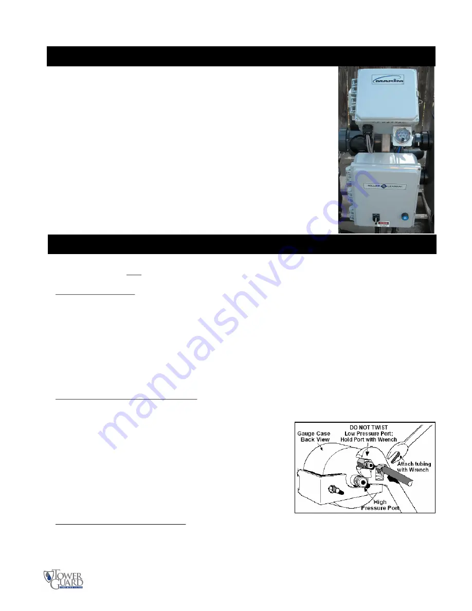
MAXIM - State-of-the-art Filter Backflush Controller


The TowerGuard Filter System is controlled by  the 

MAX IM, 

a state-of-the-art 

backflush controller designed for automatic filtration systems. The heart of the 

MAXIM

 is a programmable micro PLC, custom designed to maximize the per-

formance of your filtration system. These components are protected by a robust, 
corrosion-proof watertight enclosure.   
 
 
The 

MAX IM

  is  operated  and  adjusted  through  the  user-friendly  menu  screens 

that give the user control of all critical automatic filter functions.  The backlit 
LCD  display  provides  real-time  system  status.    The  controller  includes  a 
memory module (EEPROM) port that allows for installation of system upgrades 
and  provides  the  ability  to  download  custom,  application  specific  programs 
without the need for a computer.   


Introduction 

Installation 

The 

MAX IM

  controller is pre-installed as a component of the complete TowerGuard filtration system.  Follow 

the directions below only if it is necessary to connect electrical or gauge connections. 


Electrical Connections: 
The Maxim controller is pre-wired as part of the Automatic TowerGuard Filter System. 

Note:

 When using an exter nal power  sour ce, the input power  to the PC Board must be the same as indi-

cated on the upper left side of the Maxim Controller. Typically, the controller is either 24 volts AC, or 24 
volts DC, however some controllers use 120 volts AC or 12 volts DC. 

Additional connections to the Outputs should be made to the corresponding 

Output (+) 

and a 

Common (-) 

ter-

minal on the circuit board. The Pressure Differential Gauge and Timer ON Enable inputs are connected to a 
corresponding Input and Auxiliary Power Out (+) terminal on the Maxim circuit board. 
Review the 

Electrical Detail 

section prior to making any connections to the controller.  If requested custom in-

put/output capabilities are not described in this manual, please refer to an attached addendum. 


Differential Pressure Gauge Connections: 
Connect the pressure differential (PD) gauge to the system’s inlet (high/BLK) and outlet (low/BLU) pressure 
ports. 


WARNING: 

Failur e to use a second wr ench on the low pr essur e 

port when    tightening fittings may result in damage to the internal 
pressure tubing.   


Be sure all connection tubing is clean prior to installation on the 
gauge.  The gauge contains orifices that may become clogged by 
larger particles. 


CAUTION: 

Make sure not to foul the pr essur e or ifices with 

pipe dope or dirt, as the gauge will not operate. 


Differential Pressure Gauge Set-point: 
Adjust the front face needle contact to the desired PD set-point that will trigger a backflush cycle. The recom-
mended PD setpoint is 8-10 PSID above the “clean” gauge reading at the systems MAXIMUM flow rate. Set-
ting this gauge at low flow may result in continuous backflushing at higher flow rates, since the Pressure Dif-
ferential increases with flow rate. Typical PD gauge setpoints are between 12-15 PSID, depending on the flow 

rate. Initial factory PD Gauge setting is 12 PSID. 

Summary of Contents for TGSS-20C

Page 1: ...OWNER S MANUAL Operation and Maintenance Guide TGSS 20C TGSS 24C and TGSS 30C ...

Page 2: ...n any form mechanical electronic Internet or in any form without the written permmission of Miller Leaman Inc Toll Free 800 881 0320 Phone 386 248 0500 Fax 386 248 3033 E mail sales millerleaman com Web Site www millerleaman com Miller Leaman Inc 800 Orange Avenue Daytona Beach FL 32114 Toll Free 800 881 0320 Phone 386 248 0500 Fax 386 248 3033 E mail sales millerleaman com Web Site www millerleam...

Page 3: ... any questions concerning the system please contact our application specialists at 386 248 0500 or e mail us at sales millerleaman com The MAXIM Controller also contains a serial number to ID the software and controller type This Serial Number is located on the left side of the con troller box MAXIM SERIAL NUMBER M8 ___________ Each TowerGuard system is identified with a Serial Number to ID the sy...

Page 4: ...ry or product damage may occur Your filter was designed for specific applications It should not be modified and or used for any application other than originally specified If there are any questions regarding its application or installation contact Miller Leaman Inc ALWAYS OBSERVE THE FOLLOWING PRECAUTIONS 1 Read this manual carefully Consider the applications limitations and the potential hazards...

Page 5: ... the TowerGuard systems come in multiple sizes depend ing upon the desired flow rate Introduction to TowerGuard Automatic Filtration System Components Frame Skid The T304 stainless steel welded frame supports the system components while providing high durability and strength Filter Housing The fiberglass reinforced polyester filter housing which contains the sand media bed This housing is sized fo...

Page 6: ...p will turn off and the valves rotate to their backflush position The reverse flow lifts and churns the media bed creating a scouring action to release the captured debris This debris is then flushed out of the backflush manifold The filter is configured to be backflushed with source water from a city water supply After the backflush cycle is completed the valves rotate back to their original posi...

Page 7: ...o and from the filter to eliminate stress on the filter components 2 Manual valves should be installed in each line to allow the system to be isolated for maintenance However the user must make sure that all valves are open prior to running the system It is also recommended that unions be installed on each connection to allow for easier maintenance should the system ever have to be disconnected co...

Page 8: ...aking care not to break laterals while the last portion of media is being removed 4 If a slurry pump is unavailable open bottom drain remove as much sand media as possible by hand then flush re mainder of the media out by adding water to the inside of the filtration unit 5 The under drain stem and manifold can be replaced while in the filter Under drain laterals unscrew from the manifold in sectio...

Page 9: ...e then open the valve one and a half turns 9 Using the Pump switch HAND momentarily bump start the motor when looking at the fan at the back of the motor only long enough to verify that the motor is wired to rotate in the direction shown by the arrow 10 After confirming that the motor is rotating in the right direction start the pump 11 While observing the pressure gauge on the top of the filter r...

Page 10: ...ngs are facto ry preset at average values and do not necessarily reflect the individual needs for your system Below are recommendations on how to adjust the controller to fit your system s needs 1 The Pressure Differential PD gauge setting should be properly set once there is water flow in normal filtration mode The recommended PD setpoint is 7 PSID above the clean gauge reading at the system s MA...

Page 11: ...any leaks This should include all of the union couplings The O rings should be lubricated with silicon gasket grease to prevent them from drying and cracking Check all of the 3 way valves to make sure they are operating properly If the valves are not rotating correctly remove the tops and inspect the motor gears Contact Miller Leaman customer service if this condition exists TowerGuard City Model ...

Page 12: ...12 Figure 5 TowerGuard Sand Filter Vessel Parts List TowerGuard Side Mount Sand Filter ...

Page 13: ... 120 volts AC or 12 volts DC Additional connections to the Outputs should be made to the corresponding Output and a Common ter minal on the circuit board The Pressure Differential Gauge and Timer ON Enable inputs are connected to a corresponding Input and Auxiliary Power Out terminal on the Maxim circuit board Review the Electrical Detail section prior to making any connections to the controller I...

Page 14: ...ckflush valve actuates CW for Filtration flow This output is activated after backflushing is com plete to return water to normal flow Note delayed for 2 sec after Output 5 starts Output 2 Upper Backflush valve actuate CCW for Backflush flow This output is activated at the beginning of a back flush cycle to reverse water flow through the filter Output 4 Pump Starter This turns the pump off while th...

Page 15: ...ion while the pump is turned off for the valves to be turned back to the filtration position Status ON Valves to Filtration Screen after the pump has been turned off the valves will be turned back to the filtration position or closed This will take approximately 16 seconds During this time the display will be changed to the Status Screen or Screen 01 which will indicate that the Valves are being m...

Page 16: ...rd from screen 8 Company Contact Information screen causes the display to cycle back around to the beginning and display the Screen 1 Status Screen Also pressing the A button to scroll backwards from Screen 1 Status screen causes the display to cycle back around to the end and display the Screen 8 Company Contact Information screen Screen 4 BF Duration Screen 5 Time Since Last Screen 6 BF Counters...

Page 17: ...operating values These values should be adjusted to meet the filters backflush requirements Refer ence the filter manufacturer s owners manual for additional information Backflush Interval The user defined interval at which the system will initiate an automatic backflush cycle The backflush Interval timer resets after any backflush cycle occurs by timer PD gauge or opera tor This value is adjustab...

Page 18: ...ning of a backflush cycle as the valves are redirecting water from normal flow to backflush flow The controller will automatically turn the pump off for the duration of the Backflush cycle City Water is used for the Backflush Backflushing System is displayed when the City Water is cycling through the system in backflush mode Valves to Filtration is displayed at the end of a backflush cycle as the ...

Page 19: ...me displayed is in hours and minutes This value does not include the elapsed time when the back flush frequency timer is off either when the Status Screen reads Status Off or when the controller is physically switched off This screen also displays how the last backflush was triggered There are three possibilities 1 1 Operator the backflush was manually triggered by an operator via the status scree...

Page 20: ...of the Miller Leaman product Some states do not allow the exclusion or limitation of incidental or consequential damages so the above limitation or exclusion may not apply to you C Any failure that results from an accident purchaser s abuse neglect or failure to operate the products in accordance with the instructions provided in the owner s manual supplied with the product D Items or service that...

Reviews: