


11
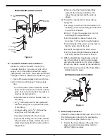
2. Use a battery powered or properly grounded
drill. Using the Clamp port as a drill guide,
drill a
7
/
32
" hole through the wall of the drain
pipe. Do NOT penetrate the opposite side of
the pipe.
3. Locate the
3
/
8
" Black Drain Tubing connected
to the Dispensing Faucet. Route to the tubing
to the Drain Clamp and trim to length.
NOTE:
When cutting the polytubing make
clean, square cuts, failing to do so could
result in poor connections and possible
leaks.
CAUTION:
The lowest point of the line
should be the point of connection to the Drain
Clamp. There should be no sag in the line as
this may cause excessive noise as the reject
water is flowing to drain.
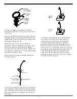
•Refer to Fig. 4. Insert the tubing into the
Drain Clamp. Make sure the tubing is
pressed all the way in to create a pressure
tight connection.
NOTE: If you want to pull the tubing out for
some reason, push the ring around the
tubing in and pull the tubing out.
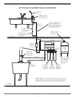
D. R.O. Manifold Assembly Installation
Locate the site per Sec. III, C.3. Various
installation sites will require different types
of mounting fasteners; be sure the fastener
selected will provide a firm, solid mounting.
A support panel may be necessary on thin
cabinet walls or to span between wall studs on
particleboard or drywall.
Do not drill through exterior cabinet walls or
leave sharp wood screw points exposed in
readily accessible cabinet interiors.
The close proximity of a dishwasher or a trash
compactor may require special fabrication of a
mounting plate.
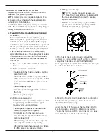
1. The mounting bracket will accept either #10
or #12 (5mm) mounting screws spaced on
6" (15 cm) centers. Allow at least 4" (10 cm)
of clearance beneath the filter housings to
accommodate filter changes. Mark the two
locations (the bracket can be used as a
template). Install the screws and tighten them
until the heads are about
5
/
8
" from the wall.
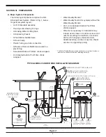
2. Locate the ¼" Red Feed Water Tubing.
Remove the red plug from the fitting labelled
“In” on the manifold and insert the tubing.
Reference the special supplement sheet in
the carton for proper connection of all tubing
and removal of plugs. Run the tubing along
its course to the Feed Water Saddle Valve,
trim to length. (Refer to Fig. 1)
Refer to Fig. 3. To the end of the red polytube
install the Compression Nut, the Plastic
Ferrule, and the Insert. Connect to the Feed
Water Saddle Valve.
3. Locate the ¼" Black Drain Tubing connected
to the Dispensing Faucet. Remove the black
plug from the fitting labelled “Drain” on the
manifold and insert the tubing. The end of the
Black Drain Tubing that should be inserted
into the “Drain” port will have a green drain
restrictor in it. If tubing needs to be trimmed
to length, carefully slit ¼" Black Drain Tubing
end that has the green drain restrictor in it
being careful not to damage the hose barb
on the drain restrictor. Remove restrictor from
tubing, make a square cut, and reinsert the
drain restrictor. Allow the tubing to relax, then
press drain restrictor firmly again to insure
proper seating.
4. Locate the ¼" yellow tubing with the tee
attached to one end. Remove the yellow plug
from the fitting labelled "Out" on the manifold
and insert the tubing.
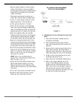
5. Locate the
3
/
8
" Blue Product Water Tubing
attached to the Dispensing Faucet. Firmly
press one end into the tee. (Refer to Fig. 1.)
The fittings will grab the tubing and seal it in
place. Make sure the tubing is pressed all the
way in to create a pressure tight connection.
NOTE:
If you want to pull the tubing out
for some reason, push the ring around the
tubing in and pull the tubing out.
6. Hang the Manifold Assembly on the
mounting screws and tighten. DO NOT
OVERTIGHTEN.
7. Remove the wrapping from the
In–Line Activated Carbon Post Filter. Slice
the
3
/
8
" Blue Polytube where it would be
convenient to install and change the In–Line
Filter. Make a clean straight cut to insure
proper connections. The “Out” port on the
In–Line Filter should be towards the faucet.
Firmly press in the tubing. The fittings will
grab the tubing and hold and seal it in place.
Make sure the tubing is pressed all the way
in to create a pressure tight connection.
Summary of Contents for MRO-35
Page 15: ...15 NOTES ...


