


Distributor of MikroElektronika: Excellent Integrated System Limited
Datasheet of MIKROE-766 - BOARD DEVELOPMENT READY PIC
Contact us: [email protected] Website: www.integrated-circuit.com
Page 18
VCC
VCC- FTDI
VCC- FTDI
RC7-RX
RC6-TX
1
2
3
4
5
6
7
8
9
10
11
12
13
14
15
16
17
18
19
20
21
22
23
24
25
26
27
28
TXD
DTR#
RTS#
VCCIO
RXD
RI#
GND
NC
DSR#
DCD#
CTS#
CBUS4
CBUS2
CBUS3
CBUS0
CBUS1
OSCO
OSCI
TEST
AGND
NC
GND
GND
VCC
RESET#
3V3OUT
USBDM
USBDP
FT232RL
U3
FT232RL
1
2
3
4
VCC
GND
D-
D+
CN1
USB B
USBDM
USBDP
VCC- 5V
VCC- USB
VCC-FTDI
VCC
VCC
RX-LED
TX-LED
LD2
LD3
VCC
J3
J2
C8
100nF
D1
MBRS140T3
FP1
FERRITE
C7
100nF
R3
2K2
R4
2K2
C5
100nF
C6
100nF
E3
10uF
D
AT
A BUS
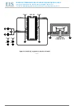
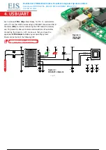
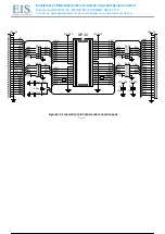
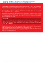
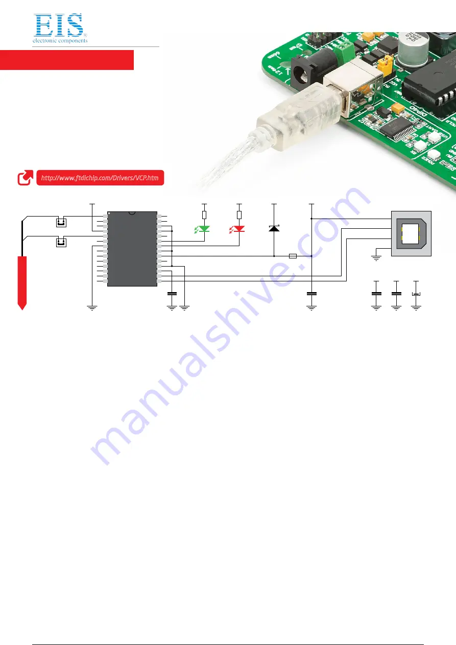
4. USB-UART
Figure 4-2:
USB-UART schematic
http://www.ftdichip.com/Drivers/VCP.htm
Fast on-board FTDI
®
chip allows Ready for PIC
®
to communicate
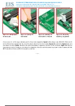
with a PC or other UART devices using a USB-UART connection. USB-B
connector (CN1) is used for connecting the USB cable. RX (receive)
and TX (transmit) LEDs will indicate communication status. Before
connecting the board to a PC, make sure that you have the
appropriate FTDI drivers installed on your operating system.
Drivers can be found at the following URL:
Figure 4-1:
connected
USB-UART
19 / 29
19 / 29