background image

Migomag ACDC 200

Model No MOMACDC

30

No.

Breakdown

Analysis

Solutions

6

No display on the 

AMP meter

Digital Amp meter 

broken

Change the meter

Cable broken/fallen 

off

Find the disconnected wire and

Connect reliably

Main PC board 

broken

Replace the PC board

7

Arc piloting not

smooth

Wrong connection 

between torch and 

welder

Check and correct according the 

manual

Argon not pure

Use 99.99% pure Argon

Tungsten electrode 

or pin broken

Use qualified Tungsten electrode

8

Power trip

First turning on 

after power long 

time (2days more) 

off

Not fault, trip caused by the 

charging filter capacitor in the 

main board, return on the power 

switch

9

Others

Please contact with the supplier/

manufacture

Summary of Contents for MOMACDC

Page 1: ...Migomag ACDC 200 TIG Inverter Part Number MOMACDC Operators Manual MIGOMAG ACDC 200 INVERTER...

Page 2: ...t service and reliability in the welding industry This product is backed by our extensive warranty To locate your nearest distributor or Repair agent please call 03 9313 3100 or visit us on the web at...

Page 3: ...Unpacking 6 Specifications 7 Know your Welder 9 Front Control Panel 10 Installation 11 Operation 13 Troubleshooting Chart 29 Spare Part Diagram 31 Spare Part List 32 Maintenance Transportation and Sto...

Page 4: ...and ventilated Do not operate the welder in humid wet or poorly ventilated areas Always have your welder maintained by a qualified technician in accordance with local state and national codes Always b...

Page 5: ...eas of Danger Caution or Warning Electrical Shock WARNING Electric arc welders can produce a shock that can cause injury or death Touching electrically live parts can cause fatal shocks and severe bur...

Page 6: ...h ear Use a lens that meets ANSI standards and safety glasses For welders under 160 Amps output use a shade 10 lens for above 160 Amps use a shade 12 Refer to the ANSI standard Z87 1 for more informat...

Page 7: ...AUTION Welding creates hot sparks that can cause injury Chipping slag off welds creates flying debris Wear protective apparel at all times ANSI approved safety glasses or shield welder s hat and ear p...

Page 8: ...immediately Store idle MOM ACDC 200 When MOM ACDC 200 is not in use store it in a secure place out of the reach of children Inspect it for good working condition prior to storage and before re use No...

Page 9: ...rnings and cautions Failure to comply with instructions could result in personal injury and or damage to product or property Please retain these instructions for future reference Description The ACDC...

Page 10: ...TIG Open Circuit Voltage 65 V VRD 12 7 V Mains Circuit Breaker Rating 29 Amps Supply plug 15 Amp Fitted Supply Cable 2 5 mm2 Three Core Heavy Duty PVC Cooling Fan cooled air drawn in through front gr...

Page 11: ...ertical Joint 1 6 3 0 1 6 2 5 50 90 DC Positive 8 12 1 0 12 20 degrees V groove 3 0 6 0 70 120 1 6 25 30 degrees X groove 6 0 12 2 5 3 2 100 150 10 14 2 4 35 45 degrees AC Pure Aluminum Alu Mag Alloy...

Page 12: ...Accessories Tig torch and regulator 1 POWER SWITCH When switch is in OFF position no power is being supplied When the switch is in the ON position power is supplied to the machine 2 INPUT POWER LEAD...

Page 13: ...oose the different procedure When selected a procedure the corresponding indicator light then use adjustment knob to adjust the parameter 6 Adjustment knob Use this knob to adjust the parameter the pa...

Page 14: ...ceptacle This welder must be grounded while in use to protect the operator from electrical shock Do not remove grounding prong or alter the plug in any way Do not use any adapters between the welder s...

Page 15: ...n voltage can affect the performance of the welder If you need to use an extension cord we recommend you check with a qualified electrician and your local electrical codes for your specific area Do no...

Page 16: ...G High voltage danger from power source Consult a qualified electrician for proper installation of receptacle at the power source This welder must be grounded while in use to protect the operator from...

Page 17: ...g mode knob to just the hot start current and arc force current can be adjusted Step 3 Press this knob choose MMA the current display shows the pre set current voltage display shows the open circuit v...

Page 18: ...ld enter into the by Parameter knob Parameter positive knob to adjust the Pre flow time to adjust the pulse peak current to adjust the Pulse width to adjust the Pulse frequency to adjust the Pulse Bac...

Page 19: ...run from when your release the trigger on the torch After you finishing welding the down slope time will start until the time period is finished and then if post gas will run for the time set and the...

Page 20: ...See the details introduction is Technical Instruction 2 5 AC pulse TIG welding Set Welding mode knob to TIG and AC DC transfer knob to AC Pulse switch set on Pulse would enter into AC pulse TIG weldin...

Page 21: ...slope time 4 2 6 1 LIFT TIG Welding Set Welding mode knob to TIG Press the electrode lightly against the work piece 1 Press the switch and the shielding gas will start to flow and a small current will...

Page 22: ...on a flat surface 3 2 Preparing the Joint Before welding the surface of work piece needs to be free of dirt rust scale oil or paint or it will create brittle and porous welds If the base metal pieces...

Page 23: ...the grounded metal melts the electrode and the flux For best performance on this unit we suggest the use of 6013 electrodes 3 5 Selecting the proper electrode There is no golden rule that determine th...

Page 24: ...e weld To ensure proper penetration and enough deposit of rod the arc must be moved slowly and evenly along the weld seam 3 6 Setting the amperage control The welder has an infinite current control It...

Page 25: ...to the welding arc can cause blindness and burns Never strike an arc or begin welding until you are adequately protected Wear flame proof welding gloves a heavy long sleeved shirt trousers without cu...

Page 26: ...the electrode in a straight line while keeping the electrode centered over the weld joint The weave bead Used when you want to deposit metal over a wider space than would be possible with a stringer...

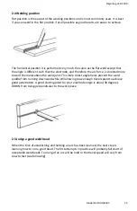
Page 27: ...e toward the metal above the weld joint This more direct angle helps prevent the weld puddle from running downward while still allowing slow enough travel speed to achieve good penetration A good star...

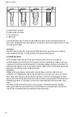
Page 28: ...chemical reaction The burning coating however forms slag The slag formation appears as an accumulation of dirty metal scale on the finished weld Slag should be removed by using a chipping hammer WARN...

Page 29: ...sumable electrode and the work piece Shielding is obtained from a welding grade shielding gas or welding grade shielding gas mixture which is generally Argon based A filler metal may also be added man...

Page 30: ...g Life Maintains balled end High current carying capacity White Ceriated 2 AC DC welding of mild steel stainless steel copper aluminium magnesium and their alloys Longer life More stable arc Easier st...

Page 31: ...50 70 1 6mm 1 6mm 15 CFH 7 LPM Butt Corner Lap Fillet 3 2mm 90 115 90 110 1 6mm 2 4mm 15 CFH 7 LPM Butt Corner Lap Fillet 4 8mm 140 165 125 150 2 4mm 3 2mm 21 CFH 10 LPM Butt Corner Lap Fillet 6 4mm 1...

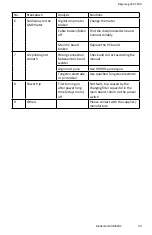
Page 32: ...o Argon input Check the flow meter and resume supplying gas to the welder Main PC board broken Replace the PC board Electromagnetism Valve broken Change the electromagnetism valve Gas path blocked Cle...

Page 33: ...the PC board 7 Arc piloting not smooth Wrong connection between torch and welder Check and correct according the manual Argon not pure Use 99 99 pure Argon Tungsten electrode or pin broken Use qualifi...

Page 34: ...Operators Manual 31 Spare Part Diagram...

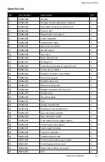
Page 35: ...85001014 Rectifier inverter circuit board 1 16 85001015 Heat sink support 4 17 85001016 Rectifier heat sink 1 18 85001017 Bottom metal panel 1 19 85001018 Rubber insulation for heat sink 1 20 8500101...

Page 36: ...llowing Periodically clean dust dirt grease etc from your welder Every six months or as necessary remove the cover panel from the welder and air blow any dust and dirt that may have accumulated inside...

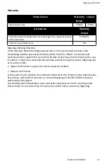
Page 37: ...als and workmanship for a period of 3 years from the date of purchase of the Product by the user If a defect in material or workmanship becomes evident during that period Migomag will at its option ei...

Page 38: ...e Seller s liability in respect of these warranties representations undertakings and guarantees is limited to the fullest extent permitted by law d Without limiting clause 21 c where the Seller sells...

Page 39: ...A Seller may at any time and from time to time alter these terms and conditions Any variation to these standard terms and conditions will not apply to any contract for a specified term that incorporat...

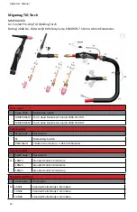
Page 40: ...RO26FX Torch Head Flexible Air Cooled 200A DC 8 MT Switch Option Stock Code Description S1 Momentary Switch PRO1MSIO 1 Button Momentary 10K Potentiometer Standard Collet Stock Code Description A 10N23...

Page 41: ...Lens use with 18CG 5 MMPRO17FX H Torch Head Flexible 6 MMPRO17 H Torch Head including Cup Gasket 7 98W18 Back Cap O Ring 8 PRO57Y02 Back Cap Long 9 PRO57Y04 Back Cap Short 10 PRO1MS Momentary Switch...

Page 42: ...a Gas Lens Body 4 0mm Bore 995795 Large Dia Gas Lens Body 3 2mm Bore Lareg Diameter Gas Lens Cup Stock Code Description L 57N75 Large Dia Gas Lens Cup 10mm Bore 57N74 Large Dia Gas Lens Cup 13mm Bore...

Page 43: ......

Reviews: