Miele SE 247 Operating Instructions Manual Download Page 21

Installation 

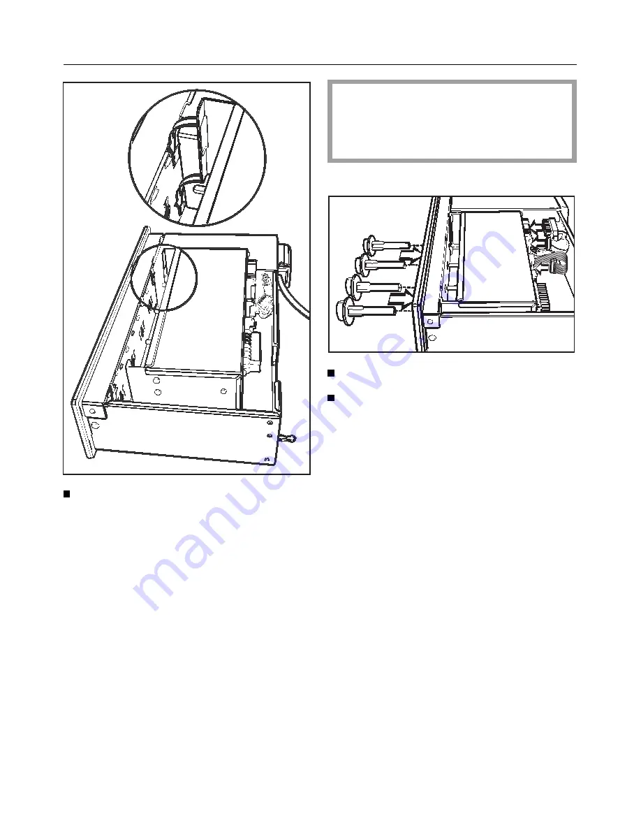
Put the hob electronic control into
the control unit.

The plugs on the control unit / hob
and the sockets on the hob elec-
tronic control are coded with the
same colour for matching.

Fit the plugs into the sockets.

Insert the knobs for the control unit
into the control facia.

21

Summary of Contents for SE 247

Page 1: ...ng instructions for hob control unit SE 247 It is essential to read these operating instructions before Q installing or using the machine to avoid the risk of accident or damage to the machine M Nr 04 697 770 ...

Page 2: ...ime 9 Safety feature 10 Operation Timer 11 Maintenance Cleaning and care Appliance front controls 15 Problem solving guide 16 After sales service 17 Preparation for use Electrical connection 18 Installation Installation in a base unit 20 Please consult the operating instructions supplied with the hob for details on its use and installation ...

Page 3: ...front left d Cooking zone control back left e Cooking zone control back right f Cooking zone control front right Data plate When the control unit has been built in the data plate can not be seen A further data plate is supplied with this appliance Please stick this into the booklet in the frame in the section After sales service 3 ...

Page 4: ...ials away please ensure they are of fered for recycling Disposal of your old machine appliance Old machines appliances contain ma terials which can be reclaimed or re cycled Please contact your dealer your waste collection centre or scrap merchant about potential recycling schemes Ensure that the machine appliance presents no danger to children while being stored for disposal See the appropriate s...

Page 5: ...sible for damage caused by improper use of the appliance Technical safety Before connecting the appliance to the mains supply make sure that the connection data given on the data plate correspond to those of the mains supply It is essential that these data match to avoid any damage to the ap pliance Consult a competent person if in doubt The electrical safety of this ap pliance can only be guarant...

Page 6: ...e the required safety of the appliance In countries which may be subject to infestation by cockroaches or other vermin pay particular attention to keeping the appliance and its surround ings in a clean condition at all times Any damage which might be caused by cockroaches or other vermin will not be covered by the appliance guaran tee Disposal of a discarded appliance Before discarding an old ap p...

Page 7: ...uttons With the push buttons you can enter the time of day enter the start of a cooking process enter the duration of a cooking pro cess enter the end of a cooking process A corresponding symbol for each push button appears in the display when ap propriate The Symbol lights up when hob zone control switched on and the relevant button pressed in 7 ...

Page 8: ...on Enter the time immediately with the button While the indicator light at the centre of the button is lit up a time can be entered or altered This can be done by pressing the button or any other button When the indicator light goes out the data input or alteration has been regis tered A symbol in the timer display shows which cooking zone is being pro grammed the front left cooking zone the front...

Page 9: ...ttons f and at the same time 12 00 and the indicator light for the button now stay on without flash ing Use the button to enter the time of day in hours minutes An entry can be made while the indica tor light for the button is on When the indicator light for the button goes out the time of day has been set and the clock display change s at one minute intervals The colon flashes 9 ...

Page 10: ...he f button until the key symbol appears in the display area The cooking zones can now not be switched on After a short time the time of day reap pears in the display area However the key symbol will appear as soon as a button is pressed To cancel the operating lock Press the f button until the key symbol in the display area disap pears After an interruption to the power supply the operating lock ...

Page 11: ... cut 12 00 and the symbols f and flash in the display If a process has been pre pro grammed the time of day can not be altered or cancelled To alter the time of day Press the buttons f and at the same time 12 00 will show constantly in the dis play Using the button enter the time of day in hours minutes To cancel the time of day Press the f and buttons twice in succession The time of day continues...

Page 12: ...ocess has been pre selected the hob zone symbol flashes next to the time of day display When the process starts running the symbol for the chosen hob zone lights up next to the time of day When the end of cooking time is reached the hob switches off automatically an audible tone sounds for approx 5 seconds the symbol for the selected hob zone and the symbol both flash If the audible tone is not sw...

Page 13: ...e end of cooking time immediately while the indicator light for the button remains on Press the button The time of day and the duration of cooking time entered appear in the dis play Use the button to postpone the end of cooking time First the time of day will appear Postponing the start of cooking time Turn the hob zone control to the re quired setting First enter the start of cooking time Press ...

Page 14: ...played This goes out as soon as the process begins g The display shows the duration of cook ing time or the time left if the process has started The end of the cooking process is dis played To change Press the corresponding button Use the button to enter the re quired time When the indicator light for the button goes out the newly se lected time is registered The time of day appears in the display...

Page 15: ...eaning and care Appliance front and control panel Use a mild cleaning agent or a dash of detergent in hot water Wipe dry with a soft cloth Do not use a scouring agent as this would scratch the surface 15 ...

Page 16: ...ent person Unauthorised repairs can be dangerous Some minor problems however can be dealt with as follows What to do if 12 00 is flashing in the timer display This is not a fault There has been an interruption to the power supply When power is restored the time of day must be entered again and the hob lock re activated 16 ...

Page 17: ... nearest authorised Customer Ser vice department address on back page When contacting the Service depart ment please quote the model and ser ial number of your appliance which are shown on the data plate Please also quote the model and serial number of your hob Space for the data plate for the control unit hob 17 ...

Page 18: ...t For extra safety it is advisable to install a residual current device with a trip cur rent of 30 mA Control unit U K The appliance is supplied with a 3 core cable for connection to a 230 240 volt 50 Hz supply Important The wire are coloured in accordance with the following code Green yellow earth Blue neutral Brown live WARNING THIS APPLIANCE MUST BE EARTHED If the connection requires a differen...

Page 19: ...e for the maximum rated load Data relating to electrical connection will be found on the data plate located at the rear of the appliance Make sure that these figures comply with the main voltage Connection of this appliance should be made via a suitable isolator which com plies with national and local regulations The appliance is supplied with a 3 core cable for connection to a 230 240 volt 50 Hz ...

Page 20: ...accessible Disconnect the mains electricity supply to the appliance Install the hob Before building in the control unit pull the control knobs out of the openings in the facia Draw out the control unit from the re taining plate Set the control unit retaining plate into the cut out base unit facia Fix the retaining plate to the side edges of the base unit cut out with 2 screws on each side 20 ...

Page 21: ...l into the control unit The plugs on the control unit hob and the sockets on the hob elec tronic control are coded with the same colour for matching Fit the plugs into the sockets Insert the knobs for the control unit into the control facia 21 ...

Page 22: ...e that no connecting cables are crushed or caught The mains cable must not come into contact with the underside of the hob Pull any superfluous cable away from the space behind the control unit when it is pushed in Push the control unit into the retain ing plate The pins of the control unit must se curely fit into the retainers on the re taining plate Fit the protective shelf under the con trol un...

Page 23: ...23 ...

Page 24: ...Alterations rights reserved 22 GB IRL ZA 1597 M Nr 04 697 770 This paper consists of cellulose which has been bleached without the use of chlorine ...

Reviews: