PW 6055/6065
en
– AU, NZ
10 291 510 / 01
17
Trade waste discharge from commercial clothes washer may require
pre-treatment as determined by the network utility operator.
Connecting the drain hose to a sink drain outlet
The drain hose with non-return valve fitted can be connected securely
to a suitable sink drain outlet.
If required, the hose can be extended to a length of 5 m. The
necessary parts can be ordered from Miele.
For a delivery head of more than 1 m (up to a max. of 1.6 m) a
replacement drain pump will need to be fitted. Please contact Miele for
advice.
Equipotential bonding
If necessary, equipotential bonding with good galvanic contact must
be guaranteed in compliance with all applicable local and national
installation specifications.
Connection material for equipotential bonding must be provided on
site or using a kit available from Miele.
Peak load / Energy management
The machine can be connected to a peak-load or energy
management system using an optional kit.
Three signals are issued by the machine via a terminal strip. The
terminal strip is labelled a, b, c, and d.
a - Output signal, Start of machine operation
b - Output signal, Machine heating request
c - Peak-load input signal, Machine heating deactivated
d - Neutral conductor
When a peak-load signal is received, the heating is deactivated and
the programme stopped. An appropriate message appears in the
display.
The programme is resumed automatically when the peak-load system
reactivates the heating.
Liquid dispensing connection
External liquid dispenser pumps with a 'container empty' indicator can
be used to dispense liquid detergents.
Only liquid dispenser pumps with their own controls or
programming facilities can be used.
It is particularly important to observe manufacturer's instructions when
using a combination of detergents, additives and special-purpose
products.
Payment system
This machine can be fitted with a single-machine payment system
(optional accessory). The necessary programming should only be
performed by a qualified agent or by Miele.
Alternatively, a wireless multi-machine system for a maximum of 8
units can be connected to a Geldkarte payment system and further
controls used to monitor machines.
Serial interface
The serial interface is provided by an additional XKM RS323 module.
The led through data interface from the XKM RS232 module conforms
with SELV (safety extra-low voltage) according to EN 60950. External
connection units must also comply with SELV.
The plug-in module is provided with a connection cable and a D-Sub
plug for connection.
Installation and anchoring
The machine must be installed on a perfectly smooth, level and firm
surface which is able to withstand the quoted loads.
The floor load created by the machine is concentrated and transferred
to the installation footprint via the machine feet.
The machine must be secured to its installation location.
The machine should be levelled in both directions with the aid of the
adjustable feet.
The anchors provided can be used to bolt the machine to the floor by
both front feet. The material provided is intended for use in bolting the
machine to a concrete floor.
Bolts and fasteners for all other floor types must be provided on site.
Plinth installation
The machine can be installed on a machine plinth (open or box plinth,
available as an optional Miele accessory) or on a concrete platform to
be provided on site.
The quality of the concrete and its strength must be assessed
according to the machine load. Ensure that any raised concrete plinth
is adequately bonded to the concrete floor below.
If the machine is installed on a concrete or masonry plinth, it must be
secured using the anchors supplied with the machine. Otherwise there
is the danger of the machine moving and falling off the plinth during
spinning.
Washer-dryer stack
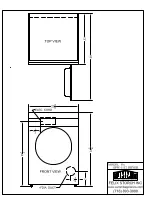
This washing machine can be installed with a Miele tumble dryer on
top of it. A WTV stacking kit (optional accessory) is required for this.
Installation of the stacking kit must be performed by a Miele service
technician or an authorised agent.
Summary of Contents for PW 6055 AV/LP
Page 3: ...PW 6055 6065 en AU NZ 10 291 510 01 3 Machine dimensions PW 6055 ...
Page 4: ...en AU NZ PW 6055 6065 4 10 291 510 01 Installation PW 6055 ...
Page 5: ...PW 6055 6065 en AU NZ 10 291 510 01 5 Washer dryer stack PW 6055 ...
Page 6: ...en AU NZ PW 6055 6065 6 10 291 510 01 Machine dimensions PW 6065 ...
Page 7: ...PW 6055 6065 en AU NZ 10 291 510 01 7 Installation PW 6065 ...
Page 8: ...en AU NZ PW 6055 6065 8 10 291 510 01 Washer dryer stack PW 6065 ...
Page 9: ...PW 6055 6065 en AU NZ 10 291 510 01 9 Installation ...
Page 10: ...en AU NZ PW 6055 6065 10 10 291 510 01 Installation ...


