Umbau- und Montageanweisung
M.-Nr. 09813684
23 von 51
Diese Unterlagen dürfen ohne unsere Genehmigung weder vervielfältigt noch Dritten zugänglich gemacht werden. Eigentumsrechte vorbehalten.
25.08.2020
Danger due to incorrectly carried out service and repair work
WARNING
Danger due to incorrectly carried out service and repair work.
There is a risk of serious damage, injury and even death if service and repair work is carried out incorrectly.
A
Service and repair work should only be carried out by a suitably qualified electrician with specialist training,
knowledge and experience.
A
All appropriate safety regulations must be taken into account.
A
Read the technical service documentation (TSD) before starting service work.
Risk of electric shock when working on a machine connected to the power supply
WARNING
Risk of electric shock when working on a machine connected to the power supply.
Even with the machine switched off, voltage is applied to components. When the machine is connected to the power
supply, supply voltage is present in the machine interior.
A
Before starting any service work, the machine must be physically disconnected from the power supply.
A
Carry out suitable measurements to ensure that no voltage is present!
DANGER
Risk of electric shock when cover/lid is not installed.
A
Only connect the machine to the power supply and operate it when the cover and/or lid is installed.
Risk of cuts
WARNING
Components are sharp.
Risk of cuts during service work.
A
Wear protective gloves.
Risk of injury
WARNING
Components have protruding edges.
Risk of injury.
A
Wear safety goggles.
Undercounter cover plate installation
Removing the lid
A
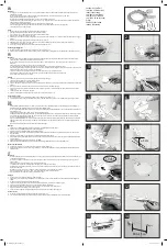
Remove the 2 top screws from the rear panel; see Fig. 2.
These screws will be needed for later installation of the cover plate.
A
Models with angled brackets:
Remove the angled brackets together with the lid; see Fig. 2.
Models with angled brackets:
The angled brackets are no longer needed.
A
All models:
Pierce the center of the screw caps with a screwdriver and pull them out; see Fig. 3.
A
Loosen the screws by a maximum of five turns.


