background image

Chapter 1: Introduction

DSS-5000 

5. The Date/Time Settings are displayed.  Tap 

Next

 to con-

tinue after making any adjustments.

Select Time 

Format

:

12-hour or 24-hour format

Select Date 

Format

:

DD/MM/YYYY, MM/DD/YYYY, or YYYY/

MM/DD

Select Time 

Zone

:

Time zone offset from Greenwich Mean 

Time

Set Date

:

Set the current date

Set Time

:

Set the current time in the selected time 

zone

6. The Test Settings are displayed.  Tap 

Next

 to continue after 

making any adjustments.

Battery 

Rating

Default: CCA (Cold Cranking Amps)

Temperature 

Units

Select Fahrenheit or Celsius

Decimal 

Separator

Select decimal point or comma

7. A list of devices connected to the tester is displayed.

To add a device, tap the plus (+) sign and follow the

on-screen instructions.  To unlink from a device, tap the

displayed serial number to select it.  Tap the trash can icon 

(

3

) to delete it.

NOTE:

 A passkey number is automatically gener-

ated once the Bluetooth pairing has been estab-

lished.

Tap the check box to require an Amp Clamp when 

performing a System Test.

8. A listing of detected Configured WiFi networks is dis-

played.

To select a network

: For initial setup, no networks will be

displayed here yet.

To add a network

: Tap the plus (+) sign, then select from

one of the displayed detected networks.
To manually add a network, tap the plus (+) sign again.

Follow the on-screen instructions to select the Network

SSID, Security, and IP Settings.  Tap 

Next

 when finished.

Use the onscreen keypad to manually enter the Network

SSID, security type, and IP settings.  If necessary, enter the

WiFi network password.  Tap 

Next

 when finished.

A confirmation screen is displayed when the analyzer has

successfully connected to the WiFi network.

To delete a network

: Tap a displayed network to select it.

Tap trash can icon (

3

) to delete it.

9.

The BMIS (

B

attery 

M

anagement 

I

nformation 

S

ystem) Ac-

count screen is displayed.
Tap 

Yes

 to connect the analyzer to an existing BMIS


account.  Enter a BMIS User Name and Password for the


analyzer to use when transmitting test data to the BMIS


database.
Tap 

No

 to skip this step.

10.

The Email Address Book screen (Admin Only) is displayed.


To add an email address

: Tap the plus (+) sign, then use


the displayed keyboard to add the address.

To edit an email address

: Tap the pencil  icon, then use


the displayed keyboard to edit the address.

To delete an email address

: Tap a displayed email address


to select it.  Tap trash can icon (

3

) to delete it.

To use the Default Email Server Settings

: Tap the gear


icon to use the default.
 

1

1

.


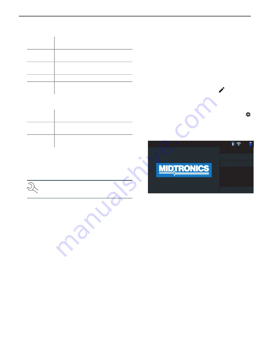
The login screen is displayed.

 93% 

Select User

Guest

admin

Add User

1

2

.


Tap a user name to access the Main Menu.

Summary of Contents for DSS-5000

Page 1: ...Guide DSS 5000 Battery Diagnostic Service System For testing 6 and 12 volt automotive 12 volt and 24 volt charging systems...

Page 2: ...iately with a mixture of water and baking soda Always wear proper safety glasses or face shield when working with or around batteries Keep hair hands and clothing as well as the analyzer cords and cab...

Page 3: ...or updating and servicing the Control ler when a WiFi network is not available Power Supply Connection Tester Pod Accessory Connector Optional For connecting an optional accessory ex Amp Clamp DMM Cab...

Page 4: ...er to a voltage source greater than 30 Vdc Connect the clamps to the tester the red clamp to the positive terminal and the black clamp to the negative terminal If you connect the clamps in the wrong p...

Page 5: ...hen select from one of the displayed detected networks To manually add a network tap the plus sign again Follow the on screen instructions to select the Network SSID Security and IP Settings Tap Next...

Page 6: ...le Test For testing out of vehicle customer batteries for possible return After New Battery Install For testing newly installed batteries in a vehicle Also includes vehicle electronics reset informati...

Page 7: ...7 8 9 0 W E R T Y U P A S D F G H J K L Z X C V B N M Back Next Thedisplayeddigitcounterwillcountupthealphanumeric characters as they are being entered on the keypad Yr Make Model Use the scrolling l...

Page 8: ...required standards Good Battery Unknown Reserve Battery meets or exceeds required standards Good Recharge Good Battery Battery is good but low on charge Fully charge the battery for optimal performan...

Page 9: ...8V 7 86V 11 61V Cranking Current 623 9A 0A Send Results Done Test Results Starter Test Test Results Starter Decision Action Cranking Normal The starter voltage is normal and the battery is fully charg...

Page 10: ...se or heavily corroded clean or replace the cable and retest HIGH OUTPUT Alternator voltage to the battery exceeds normal limits of a functioning regulator Check for loose and normal ground connection...

Page 11: ...ng of CCA 100 to 3000 IEC A International Electrotechnical Commission 100 to 1000 EN A Europa Norm 100 to 1700 EN2 A Europa Norm 100 to 1700 Battery Rating Enter the Battery Rating Units value 4 Align...

Page 12: ...el Use the scrolling lists to select the manufacture date manufacturer and vehicle model Once entered a list of matching previously tested vehicles is displayed Search Library 93 Vehicle Year 3 vehicl...

Page 13: ...ttery meets or exceeds required standards Test again in 90 days or at next service opportunity Send Results System Test Done Test Results Battery 93 2005 Honda Civic 1HGEM225X5Lxxxxxx 4 10 2017 2 54 P...

Page 14: ...If no Amp Clamp is being used begin the System Test at Step 4 2 Tap Continue to zero out the clamp or Skip if the Amp Clamp is not being used 3 With the engine and electrical loads off place the Amp...

Page 15: ...when engine is running Check all alternator connections including to the battery Clean or replace if necessary and retest If the belts and connections are in good working condition replace alternator...

Page 16: ...meter measures voltage between two points in a circuit The voltmeter is connected in parallel with the circuit AC Volt Meter 93 0 17 V AC 1 Connect the DMM test lead to the accessories port on the Dia...

Page 17: ...ange and display the measurement 5 When finished press END 6 Tap Back to return to the Digital Multimeter screen Diode Drop The diode test measures the voltage drop across components such as diodes Di...

Page 18: ...0 05 2 120 Vrms Vac 0 24 Vac rms 0 01 Vac 0 1 3 120 Vrms Adc 0 70 A 0 01 A 3 of reading 1A 1000 Arms 0 700 A 0 1 A 3 of reading 1A 1000 Arms Aac 0 70 A 0 01 A 3 of reading 1A 1000 Arms 0 700 A 0 1A 3...

Page 19: ...Failed Replace Battery Aborted Badcell Short Replace Invalid Test Remote Post Aborted 24V Side Post Out Of Balance Totals By Test Type Displays test totals by test type HD Battery Pack Test After New...

Page 20: ...include non critical Notifications Unread Critical Messages Read Critical Messages 1 Tap Messages on the Main Menu screen Messages 93 Critical 1 2 BMIS Authentication failed Check login credentials A...

Page 21: ...WiFi Self Diagnostics WiFi Printer Self Diagnostics CVG Self Diagnostics Tester Pod Self Diagnostics Display Self Diagnostics Touchscreen Self Diagnostics WiFi Self Diagnostics Tests connectivity to t...

Page 22: ...tup function detects and displays a list of connected and available WiFi and Bluetooth printers NOTE WiFi network communication must be suc cessfully established before a printer or printers can be de...

Page 23: ...il sever settings 2 Tap to enter or modify existing server settings includ ing Host Port Login Password SMTP Authorization En able TLS and From Email Address information 3 Tap to clear all server sett...

Page 24: ...Log into a BMIS account Shop Information Admin Only Access default Shop Information including Store Name address and phone number Also access battery test defaults including rating temperature units a...

Page 25: ...d Add Tester Pod 1 Tap to add a device 2 Move the device to be linked within 30 feet of the Control ler turn on the device then tap 3 A list of detected devices is displayed Tap next to the desired de...

Page 26: ...nostic Device Version CVG 2 Device Version No Device Configured OS Version Factory Preset Use this function to return the tool to the original as built configuration including all history and test set...

Page 27: ...ation Single Battery or Dual Batteries Battery Application Automotive Marine Powersport Group 31 Commercial 4D 8D Lawn and Garden Battery Post Top Post Side Post Dual Post Test Location Top Post Side...

Page 28: ...era Hold Steady Hold Controller steady when scanning the VIN barcode This allows the user to clearly see the bar code and allows the camera to focus on it Acquire VIN 93 Flashlight Fill the viewfinder...

Reviews: