6
HARDWARE ALIGNMENT
1. For level reference, take a signal measurement at the input and output of the RX audio path’s breaking point
component by modulating the receiver with a full quieting signal and at full modulation. That’s 5 kHz for a
wide band radio and 2.5 kHz for a narrow band radio of a 1 KHz tone.
2.
For the TX signal level, speak normally into the microphone while monitoring the TX breaking point. For a
higher level, say “FOUR” and document the levels. If it is possible to inject a 1 kHz tone into the microphone
stage, set that as 3 kHz for wide band or 1.5 kHz for narrow band as a reference.
3. To set up the RX level correctly on the TVS-2 (after installation into the radio), modulate the radio receiver at
full quieting with a 1250 Hz tone at .7 to .8 kHz for wide band or .35 to .4 kHz for narrow band.
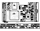
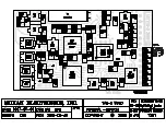
4. To adjust the RX input pot, monitor with an oscilloscope at IC-6 Pin 7 until it triggers at the step 3 levels.
5. Adjust the RX output pot to match the reference level documented from step 1 output level. If the output level
cannot be obtained call Midian for further details.
6. For the TX levels, set the TX input pot so that the level at IC-9 Pin 1 is just below clipping by speaking loudly
into the microphone with the scrambler in scramble mode.
7.
With the scrambler in the clear mode, adjust the TX output pot for the documented level from step 2 output
level.
8.
With the scrambler in scramble mode, key the radio with no audio and observe the TVS-2 sync-packets on a
communications analyzer. Make sure the sync-packets are as close to full modulation as possible.
For further details for aligning the RX and TX lines, refer to the TVS-2 Technical Reference Manual.


