background image

2. OPERATION MODES AND INSTRUCTIONS

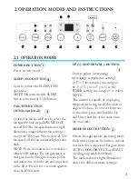
POWER BUTTON

 Power switch on/off.

SLEEP/ECO BUTTON

 Used to initiate the SLEEP/ECO 
 operation. 
 NOTE: On some models SLEEP 
 button is instead of  ECO button.

FAN/ION BUTTON
(ION is optional)

 Control the fan speed. Press to select the
 fan speed in four steps-LOW, MED, HI 
 and AUTO.The fan speed indicator light 
 illuminates under different fan settings 
 except AUTO speed. When select AUTO 
 fan speed, all the fan indicator lights turn 
 dark. 
 NOTE: Press this button for 3 seconds to
 initiate ION feature.The ion generator is 
 energized and will help to remove pollen 
 and impur ities from the air, and trap them
 in the filter. Press it for 3 seconds again to 
 stop the ION feature.

UP(+) AND DOWN(-) BUTTON

 Used to adjust (increasing/
decreasing)  temperature settings
 (2 

℉/

1

increments) in a range of

 62 

(17

) to 88

(30

) or the 

TIMER setting in a range of  0~24hrs.
 NOTE: 
 The control is capable of  displaying 
 temperature in degrees Fahrenheit or
 degrees Celsius. To convert from one
 to the other, press and hold the Up 
 and Down buttons at the same time, 
 for 3 seconds.

MODE SELECT BUTTON

 Selects the appropriate operating mode. 
 Each time you press the button, a mode
 is selected in a sequence that goes from  
 AUTO, COOL, DRY, FAN and HEAT
 (cooling only models without). 
 The mode indicator light illuminates 
 under the different mode settings..

2.1  OPERATION MODES

1

2

3

4

5

1

1

2

3

4

4

5

6

7

8

9

Optional

Summary of Contents for MYPD-12CRN1-QB6

Page 1: ...NUAL PD SERIES Models MPPD 12CRN1 BH9 MPPD 14CRN1 BH9 MPPD 12HRN1 BH9 MPPD 14HRN1 BH9 PD standard panel PD1 PD3 PDA PDB panel used for small body MYPD 12CRN1 QB6 Cooling only Heat pump Electronic heat...

Page 2: ...1 DIMENSION W H D Unit Dimension Single hose small body Single hose Double hose W H D mm inch 454 17 9 467 18 4 467 18 4 700 27 6 765 30 1 765 30 1 365 14 4 397 15 6 478 18 8...

Page 3: ...r ities from the air and trap them in the filter Press it for 3 seconds again to stop the ION feature UP AND DOWN BUTTON Used to adjust increasing decreasing temperature settings 2 1 increments in a r...

Page 4: ...Temp Sensing feature point the remote control towards the unit and press the Follow Me Temp Sensing button The remote display is actual temperature at its location The remote control will send this si...

Page 5: ...TO mode you can not select the fan speed TIMER OPERATION When the unit is on press the Timer button will initiate the Auto off stop program the TIMER OFF indicator light illuminates Press the UP or do...

Page 6: ...defrosting at cooling mode or drying mode At cooling or drying mode when T2 2 for 3 minutes continuously it enters into Auto defrosting function with compressor turning off If water level is below S1...

Page 7: ...0 6 27 9 1245 129 2 54 2 959 33 8 1 33 3269 82 4 28 8 7198 131 55 2 8442 35 6 2 31 5635 84 2 29 8 3357 132 8 56 2 7382 37 4 3 29 9058 86 30 7 9708 134 6 57 2 6368 39 2 4 28 3459 87 8 31 7 6241 136 4 5...

Page 8: ...When T1 TS 2 select the setting temperature TS for Cooling operation s temperature The indoor fan motor operates at Auto fan mode with speed uncontrolled and not changed The speed of indoor fan can be...

Page 9: ...working And outdoor fan will stop for a delay of 5 seconds b When T1 59 15 outdoor fan operates and compressor will restart operation after 15seconds The speed can t be controlled at drying mode and i...

Page 10: ...etting speed When compressor stops indoor fan motor also stops the unit can be set at high mid low auto speed Indoor fan motor will be off for a delay of 20 seconds becaues of compressor being off by...

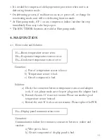
Page 11: ...vaporator temperature sensor error E3 Condenser temperature sensor error Causation a Port of temperature sensor is loose b Temperature sensor is bad c Circuit component is bad Solution a Check the con...

Page 12: ...f it can not resume after 2 minutes please replace the PCB 4 2 Protection code and Solution P1 Water full protection Causation Water in tank is full Solution Connect the drain hose and drain the colle...

Page 13: ...ve the heat sources if possible c Connect the duct and make sure it can function properly d Decrease the TS e Clean the air filter Noisy or vibration Causation The ground is not level or not flat enou...

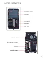
Page 14: ...5 INTERNAL STRUCTURE Temperature sensor Evaporator Centrifugal fan Compressor Water pump Indoor fan motor Capacitor of compressor Condenser Water level sensor...

Page 15: ...Capacitor of fan motor Electronic control box Display board Temperature sensor Display board Water level switch Louver motor Outdoor motor Indoor motor Relay Power on off...

Page 16: ...bly 1 5 Horizontal louver 6 Cover of electronic control box 1 6 Bracket 7 Suction pipe assembly 1 7 Gear wheel 8 Discharge pipe assembly 1 7 Gear wheel 10 Capillary assembly 1 8 Louver motor 11 Evapor...

Page 17: ...fugal fan 27 7 Bracket of water level sensor 32 6 Power cord 27 8 Micro switch 33 Capacitor box 27 9 Bracket of Micro switch 34 Capacitor of compressor 27 10 Dobber case 35 Fasten board of Capacitor 2...

Page 18: ...2 8 Capacitor box 27 17 Top cover of Shaded pole motor 3 Dobber 27 18 Bottom cover of Shaded pole motor 5 Electronic control box assembly 27 19 Drain Connector 5 1 Electronic control box 27 20 Connec...

Page 19: ...itioning Equipment Co Ltd RAC Overseas Sales Company Midea headquarter building No 6 Midea Avenue Beijiao ShunDe Foshan GuangDong P R C 528311 Website www mideaaircon com Midea America Corporation Cus...

Reviews: