background image


1

1. Precaution 

1.1 Safety Precaution 


To prevent injury to the user or other 

people and property damage, the following 

instructions must be followed. 


Incorrect operation due to ignoring 

instruction will cause harm or damage.   


Before service the unit, be sure to 

read this service manual at first. 


1.2 Warning 


Installation 


Do not use a defective or underrated 

circuit breaker. Use this appliance on a 

dedicated circuit. 

There is risk of fire or electric shock. 


For electrical work, contact the dealer, 

seller, a qualified electrician, or an 

authorized service center. 

Do not disassemble or repair the product, 

there is risk of fire or electric shock. 


Always ground the product. 

There is risk of fire or electric shock. 


Install the panel and the cover of 

control box securely. 

There is risk of fire of electric shock. 


Always install a dedicated circuit and 

breaker. 

Improper wiring or installation may cause   

electric shock. 


Use the correctly rated breaker of 

fuse. 

There is risk of fire or electric shock. 


Do not modify or extend the power 

cable. 

There is risk of fire or electric shock. 


Do not install, remove, or reinstall the 

unit by yourself (customer). 

There is risk of fire, electric shock, explosion, 

or injury. 


Be caution when unpacking and 

installing the product. 

Sharp edges could cause injury, be especially 

careful of the case edges and the fins on the 

condenser and evaporator. 


For installation, always contact the 

dealer or an authorized service center. 


Do not install the product on a 

defective installation stand. 


Be sure the installation area does not 

deteriorate with age. 

If the base collapses, the air conditioner could 

fall with it, causing property damage, product 

failure, and personal injury. 


Do not let the air conditioner run for a 

long time when the humidity is very high 

and a door or a window is left open. 


Take care to ensure that power cable 

could not be pulled out or damaged during 

operation. 

There is risk of fire or electric shock. 


Do not place anything on the power 

cable. 

There is risk of fire or electric shock. 


Do not plug or unplug the power 

supply plug during operation. 

There is risk of fire or electric shock. 


Do not touch (operation) the product 

with wet hands. 


Do not place a heater or other 

appliance near the power cable. 

There is risk of fire and electric shock. 


Do not allow water to run into 

electrical parts. 

It may cause fire, failure of the product, or 

electric shock. 


Do not store or use flammable gas or 

combustible near the product. 

There is risk of fire or failure of product. 


Do not use the product in a tightly 

closed space for a long time. 

Oxygen deficiency could occur. 


When flammable gas leaks, turn off 

the gas and open a window for ventilation 

before turn the product on. 


If strange sounds or smoke comes 

from product, turn the breaker off or 

disconnect the power supply cable. 

Summary of Contents for MCHS-09NIH1

Page 1: ...Installation MUST conform with local building codes or in the absence of local codes with the National Electrical Code NFPA70 ANSI C1 1993 or current edition and Canadian Electrical Code Part1 CSA C...

Page 2: ...and the elevation 17 7 4 Installation for the first time 18 7 5 Adding the refrigerant after running the system for many years 19 7 6 Re installation while the indoor unit need to be repaired 19 7 7 R...

Page 3: ...ul of the case edges and the fins on the condenser and evaporator For installation always contact the dealer or an authorized service center Do not install the product on a defective installation stan...

Page 4: ...away properly A bad connection may cause water leakage Keep level even when installing the product It can avoid vibration of water leakage Do not install the product where the noise or hot air from th...

Page 5: ...of the same type Do not mix old and new batteries or different types of batteries There is risk of fire or explosion Do not recharge or disassemble the batteries Do not dispose of batteries in a fire...

Page 6: ...ames of Indoor Outdoor units Series Capacity Indoor units Outdoor units Inverter 9k MEHS 09NiH2 MCHS 09NiH2 MEHS 09NIH1 MCHS 09NIH1 12k MEHS 12NIH2 MCHS 12NiH2 MEHS 12NIH1 MCHS 12NIH1 18k MEHS 18NIH2...

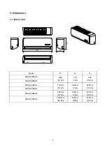
Page 7: ...H Model W D H MEHS 09NiH2 680 26 8in 178 7 0in 255 10 0in MEHS 09NIH1 MEHS 12NiH2 770mm 30 3in 188mm 7 4in 255mm 10 0in MEHS 12NIH1 MEHS 18NIH2 905mm 35 6in 198mm 7 8in 275mm 10 8in MEHS 22NIH2 1030m...

Page 8: ...170 6 7in 45 1 8in 65mm 2 56in MEHS 09NIH1 MEHS 12NIH2 95mm 3 7in 170mm 6 7in 45mm 1 8in MEHS 12NIH1 MEHS 18NIH2 80mm 3 1in 100mm 3 9in 45mm 1 8in Model R mm L mm H mm Dimension of installation hole...

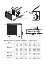
Page 9: ...4in 540 21 3in 757 29 8in 458 18 0in 250 9 8in MCHS 09NIH1 660mm 26 0in 265mm 10 4in 540mm 21 3in 732mm 28 8in 458mm 18 0in 276mm 10 9in MCHS 12NIH1 660mm 26 0in 265mm 10 4in 540mm 21 3in 732mm 28 8in...

Page 10: ...INDOOR OUTDOOR LIQUID SIDE GAS SIDE HEAT EXCHANGE EVAPORATOR HEAT EXCHANGE CONDENSER COMPRESSOR 2 WAY VALVE 3 WAY VALVE CHECK VALVE Heating Model only CAPILIARY TUBE REVERSING VALVE Heating Model onl...

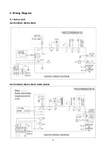
Page 11: ...9 6 Wiring Diagram 6 1 Indoor Unit MEHS 09NiH1 MEHS 12NiH1 MEHS 09NiH2 MEHS 12NiH2 MEHS 18NiH2...

Page 12: ...10 MEHS 22NiH2...

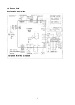
Page 13: ...11 6 2 Outdoor Unit MCHS 09NiH1 MCHS 12NiH1...

Page 14: ...12 MCHS 09NiH2 MCHS 12NiH2...

Page 15: ...13 MCHS 18NiH2 MCHS 22NiH2...

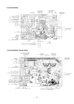
Page 16: ...14 For MCHS 12NiH2 For MCHS 09NiH1 MCHS 12NiH1...

Page 17: ...15 For MCHS 09NiH2 For MCHS 18NiH2...

Page 18: ...16 For MCHS 22NiH2...

Page 19: ...re selecting the cable fuse and switch 7 3 Pipe length and the elevation Models Pipe size Gas Liquid MEHS 09NiH2 MCHS 09NiH2 3 8in 9 52mm 1 4in 6 35mm MEHS 09NIH1 MCHS 09NIH1 3 8in 9 52mm 1 4in 6 35mm...

Page 20: ...the manifold valve 5 Operate the vacuum pump to evacuate 6 Make evacuation for 30 minutes and check whether the compound meter indicates 0 1Mpa 14 5Psi If the meter does not indicate 0 1Mpa 14 5Psi af...

Page 21: ...air from the charge hose Open the valve at the bottom of the cylinder and press the check valve on the charge set to purge the air be careful of the liquid refrigerant 3 Put the charging cylinder onto...

Page 22: ...r use a torque wrench to tighten the flare nut on the 2 way valve 4 Check the gas leakage Check the flare connections for gas leakage 5 Discharge the refrigerant Close the valve on the charging cylind...

Page 23: ...ow side on the charge set and charge the system with liquid refrigerant If the system cannot be charge with the specified amount of refrigerant or can be charged with a little at a time approximately...

Page 24: ...is used beyond the above conditions certain safety protection features may come into operation and cause the unit to operate abnormally 2 The room relative humidity should be less than 80 If the air c...

Page 25: ...ay board Defrost Indicator This indicator illuminates when the air conditioner starts defrosting automatically or when the warm air control feature is activated in heating mode Run indicator Flash at...

Page 26: ...e the indoor fan will be also controlled by anti cold wind function 9 3 7 Compressor preheating functions Preheating permitting condition If T4 outdoor ambient temperature 3 and the machine connects t...

Page 27: ...r operation frequency If users switch on AC by remote controller the compressor will run at the Fmax frequency for 7 minutes according to the outdoor ambient temp During the 7 minutes the frequency li...

Page 28: ...ode indoor fan runs all the time and the speed can be selected as high medium low and auto Auto fan in cooling mode acts as follow 4 3 High Low 1 Medium 1 5 9 4 3 Heating Mode 9 4 3 1 Compressor runni...

Page 29: ...s limited by the current I3HEAT I2HEAT I1HEAT Off Decrease Hold Resume I3HEAT I2HEAT I1HEAT mean different running current value Off Compressor stops Decrease Decrease the running frequency to the low...

Page 30: ...ps more than 5 or not Condition of ending defrosting If any one of the following items is satisfied the defrosting will finish and the machine will turn to normal heating mode T3 rises to be higher th...

Page 31: ...n cooling mode 9 4 5 5 The outdoor fan operates the same as in cooling mode 9 4 6 Forced operation function 9 4 6 1 Enter forced operation function When the machine is off pressing the touch button wi...

Page 32: ...sleep function will be cancelled when reaching the setting time If the timing is more than 7 hours the machine will not stop until reaches the setting time in sleep mode 9 4 9 Auto Restart function Th...

Page 33: ...electricity power in capacitor Electrolytic Capacitors HIGH VOLTAGE CAUTION For other models please connect discharge resistance approx 100 40W or soldering iron plug between terminals of the electro...

Page 34: ...T2 open circuit or short circuit 7 times X EC Refrigerant leakage detection 2 times O F1 Outdoor temperature sensor T4 open circuit or short circuit 3 times O F2 Condenser coil temperature sensor T3...

Page 35: ...CHS 12NiH2 There s a LED light on the outdoor PCB which is blue color After power on it will be slow flash 0 2Hz when the unit is in standby and quick flash 2 5Hz if the unit has some problems it will...

Page 36: ...MCHS 09NiH1 MCHS 12NiH1 There s a LED light on the outdoor PCB which is blue color After power on it will be slow flash 0 2Hz when the unit is in standby and quick flash 2 5Hz if the unit has some pr...

Page 37: ...for the PCB POWER display LED 4 is a yellow light After power on it will be slow flash 0 2Hz when the unit is in standby and quick flash 2 5Hz if the unit has some problems LED 1 green and LED2 red a...

Page 38: ...ight and for the PCB POWER display LED 2 is a yellow light After power on it will be slow flash 0 2Hz when the unit is in standby and quick flash 2 5Hz if the unit has some problems LED 4 green and LE...

Page 39: ...ction or IGBT over strong current protection X P0 4 Over voltage or too low voltage protection O O P1 5 Over voltage or too low voltage protection O P1 6 Inverter compressor drive error X P4 7 Inverte...

Page 40: ...eive feedback from EEPROM chip Supposed causes Installation mistake PCB faulty Trouble shooting EEPROM a read only memory whose contents can be erased and reprogrammed using a pulsed voltage For the l...

Page 41: ...lution E1 Error Code E1 Malfunction decision conditions Indoor unit does not receive the feedback from outdoor unit during 110 seconds and this condition happens four times continuously Supposed cause...

Page 42: ...l move alternately between 50V to 50V If the outdoor unit has malfunction the voltage will move alternately with positive value While if the indoor unit has malfunction the voltage will be a certain v...

Page 43: ...and solution E2 Error Code E2 Malfunction decision conditions When PCB does not receive zero crossing signal feedback for 4 minutes or the zero crossing signal time interval is abnormal Supposed caus...

Page 44: ...tion E3 Error Code E3 Malfunction decision conditions When indoor fan speed keeps too low 300RPM for certain time the unit will stop and the LED will display the failure Supposed causes Wiring mistake...

Page 45: ...ck GND 0V 4 White Vcc 14 17 5V 5 Yellow Vsp 0 5 6V 6 Blue FG 14 17 5V 2 Outdoor DC Fan Motor control chip is in outdoor PCB Power on and check if the fan can run normally if the fan can run normally t...

Page 46: ...re sensor diagnosis and solution E5 Error Code E5 Malfunction decision conditions If the sampling voltage is lower than 0 06V or higher than 4 94V the LED will display the failure Supposed causes Wiri...

Page 47: ...the compressor just starts running as Tcool In the beginning 5 minutes after the compressor starts up if T2 Tcool 2 does not keep continuous 4 seconds and this situation happens 3 times the display a...

Page 48: ...Code P0 Malfunction decision conditions When the voltage signal that IPM send to compressor drive chip is abnormal the display LED will show P0 and AC will turn off Supposed causes Wiring mistake IPM...

Page 49: ...47 For example P U P V Note The photos below are only for reference it s may be not same totally with the ones on your side...

Page 50: ...48 P W P N...

Page 51: ...ion decision conditions An abnormal voltage rise or drop is detected by checking the specified voltage detection circuit Supposed causes Power supply problems System leakage or block PCB faulty Troubl...

Page 52: ...ompressor top diagnosis and solution P2 Error Code P2 Malfunction decision conditions If the sampling voltage is not 5V the LED will display the failure Supposed causes Power supply problems System le...

Page 53: ...bnormal inverter compressor drive is detected by a special detection circuit including communication signal detection voltage detection compressor rotation speed signal detection and so on Supposed ca...

Page 54: ...from PCB measure the resistance value with a tester Temperature Sensors Room temp T1 sensor Indoor coil temp T2 sensor Outdoor coil temp T3 sensor Outdoor ambient temp T4 sensor Compressor discharge t...

Page 55: ...243 0 38991 2 28 39 8239 38 100 5 62961 78 172 1 25423 118 244 0 37956 1 30 37 1988 39 102 5 39689 79 174 1 2133 119 246 0 36954 0 32 35 2024 40 104 5 17519 80 176 1 17393 120 248 0 35982 1 34 33 326...

Page 56: ...5 222 8 36 97 34 32 76 169 7 82 116 241 2 357 3 27 211 4 37 99 32 94 77 171 7 566 117 243 2 294 2 28 200 7 38 100 31 62 78 172 7 321 118 244 2 233 1 30 190 5 39 102 30 36 79 174 7 086 119 246 2 174 0...

Page 57: ...55 Appendix 3 10 11 12 13 14 15 16 17 18 19 20 21 22 48 50 52 54 56 58 60 62 64 66 68 70 72 23 24 25 26 27 28 29 30 31 32 33 34 35 74 76 78 80 82 84 86 88 90 92 94 96 98...

Page 58: ...ng Measure the resistance value of each winding by using the tester Position Resistance Value DA108X1C 23EZ DA108X1C 20FZ3 DA130M1C 31FZ DA150S1C 20FZ Blue Red 1 1 20 68 0 71 20 68 1 77 20 68 0 95 20...

Page 59: ...eral M P N U N U V V W W Red 4 Indoor AC Fan Motor Measure the resistance value of each winding by using the tester Position Resistance Value RPG13B RPG15A RPG20B RPG28H RPG45B Black Red 530 8 20 68 B...

Page 60: ...DT IDT 75 23 89 85 29 44 95 35 105 40 56 115 46 11 PSI 70 59 119 113 117 125 147 PSI 75 63 124 120 126 132 155 PSI 80 67 135 129 132 140 162 ODT IDT 75 23 89 85 29 44 95 35 105 40 56 115 46 11 MPA 70...

Page 61: ...37 33 2 78 0 56 27 23 2 78 5 17 13 8 33 10 56 PSI 55 439 413 367 330 302 PSI 65 471 435 386 368 339 PSI 75 489 457 403 381 362 ODT IDT 57 53 13 89 11 67 47 43 8 33 6 11 37 33 2 78 0 56 27 23 2 78 5 17...

Reviews: