background image

ENGLISH

15

IX. GAS SUPPLY (gas ovens only)

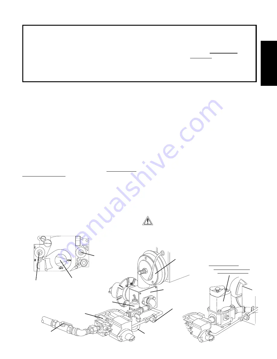
Figure 2-26 - Gas Burner and Piping Assembly

Manual

shutoff valve

Pilot pressure tap

(where pilot gas

pressure is measured)

Combination Gas

Control Valve

(Safety Regulator)

Inlet pressure tap

(where incoming

gas pressure is

measured)

Manifold pressure tap

(where manifold gas

pressure is measured)

On/Off Knob

Always leave in

“ON” position

Low Flame

Bypass Line

High Flame

Solenoid Valve

Burner

Blower

Gas Burner

Model PS360EWB Only

Modulating gas valve

NOTE:  

PS360EWB ovens use a

modulating gas valve INSTEAD OF

a high flame solenoid valve and

low-flame bypass line.

SECTION 2 - INSTALLATION

A. Gas Utility Rough-In Recommendations

The following gas system specifications are STRONGLY

RECOMMENDED.  Deviating from these recommendations

may affect the baking performance of the oven.

Gas Meter

•

One or two oven cavities:  750 cfh meter

•

Three or four oven cavities:  1200 cfh meter

Gas Line

•

DEDICATED LINE from the gas meter to the oven

•

2" (50.8mm) pipe for natural gas

•

1-1/2" (38.1mm) pipe for propane

•

Maximum length:  200' (61m).  Each 90° elbow equals 7'

(2.13m) of pipe.

B. Connection

Check the oven’s gas supply requirements before making the

gas utility connection.  Gas supply requirements are listed on the

oven’s serial plate (Figure 2-23) and in the Gas Orifice and

Pressure Specifications table (Page 5 of this manual).
Check the serial plate to determine the type of gas (Propane or

Natural) to be used with the oven.
Refer to the instructions in the gas hose package (included in the

Installation Kit) before connecting the gas line.  One gas line

connection method is shown in Figure 2-25; however, compliance

with the applicable standards and regulations is mandatory.
Inlet, regulated, and pilot gas pressure readings can be taken

using a “U” tube manometer at the tap locations shown in Figure

2-26.

CAUTION

DURING PRESSURE TESTING NOTE ONE OF THE FOLLOWING:
1. The oven and its individual shutoff valve must be discon-

nected from the gas supply piping system during any pres-

sure testing of that system at test pressure in excess of 1/

2 psi (3.45 kPa).
2. The oven must be isolated from the gas supply piping

system by closing its individual manual shutoff valve during

any pressure testing of the gas supply piping system at test

pressure equal to or less than 1/2 psi (3.45 kPa).

3. If incoming pressure is over 14” W.C. (35mbar), a sepa-

rate regulator MUST be installed in the line BEFORE the

individual shutoff valve for the oven.

WARNING: 

To prevent damage to the control valve regula-

tor during initial turn- on of gas, it is very important to open

the manual shutoff valve very slowly.
After the initial gas turn-on, the manual shutoff valve must

remain open except during pressure testing as outlined in

the above steps or when necessary during service mainte-

nance.

NOTE

The installation must conform with local codes or in the absence

of local codes, with the National Fuel Gas Code, ANSI Z223.1-

latest edition.
In Australia, the installation must conform with AGA Code AG601

and with any requirements of the appropriate statutory authority.
CANADIAN:

CAN/CGA-B 149.1 Natural Gas Installation Code

CAN/CGA-B 149.2 Propane Installation Code

Certain safety code requirements exist for the installation of gas

ovens; refer to the beginning of Section 2 for a list of the

installation standards. In addition, because the oven is equipped

with casters, the gas line connection shall be made with a

connector that complies with the Standard for Connectors for

Movable Gas Appliances, ANSI Z21.69 (in U.S.A.), or, if appli-

cable, Connectors for Movable Gas Appliances, CAN/CGA-6.16

(in Canada), as well as a quick-disconnect device that complies

with the Standard for Quick-Disconnect Devices for Use With

Gas Fuel, ANSI Z21.41 (in U.S.A.), or, if applicable, Quick-

Disconnect Devices for Use With Gas Fuel, CAN1-6.9 (in Canada).

C. Gas Conversion

Where permitted by local and national codes, it is possible to

convert ovens from natural  to propane gas, or from propane to

natural gas.  Use the appropriate Middleby Marshall Gas

Conversion Kit for the specific oven model.

WARNING

The terms of the oven's warranty require all start-ups,

conversions and service work to be performed by a Middleby

Marshall Authorized Service Agent.

Summary of Contents for PS300F

Page 1: ...23 Rev B V3 5 00 Models PS310 PS314 PS360 360Q 360S PS360WB PS360EWB PS360WB70 Combinations Single Lower Oven Single Upper Oven on Stand DoubleOven Two Stack TandemOven Double Two Stack TandemOven Mid...

Page 2: ...call the emergency phone number of your local Gas Company They will have personnel and provisions available to correct the problem FOR YOUR SAFETY Do not store or use gasoline or other flammable vapor...

Page 3: ...g 9 B Stands 9 TABLEOF CONTENTS IV THERMOCOUPLEINSTALLATION 9 V TANDEMOVENASSEMBLY 10 VI CONVEYORINSTALLATION 12 A All Non Tandem Ovens 12 B Tandem Oven Models 13 VII FINALASSEMBLY 13 VIII ELECTRICAL...

Page 4: ...0mm SECTION1 DESCRIPTION I OVEN USES PS300 Series Ovens can be used to bake and or cook a wide variety of food products such as pizza pizza type products cookies sandwiches and others II OVEN COMPONE...

Page 5: ...oes not use a bypass orifice D Electrical specifications for gas fired ovens per oven cavity Main Blower Control Current Voltage Circuit Voltage Phase Freq Draw Poles Wires PS310 314 360 360Q 208 240V...

Page 6: ...manual WARNING The oven must be installed on an even level non flammable flooring and any adjacent walls must be non flammable Recommended minimum clearances are specified in the Description section o...

Page 7: ...bleClamp 27276 0001 1 1 1 8 Screw 2PT 10 16 x 3 4 HWH 21292 0001 2 2 14 9 Owner s Operating and Installation Manual 41823 1 1 1 10 Authorized Service Agency Listing 1002040 1 1 1 NOTE The 4 swivel cas...

Page 8: ...etrimental effects can result from extreme seasonal hot and cold temperatures from the outdoors NOTE Return air from the mechanically driven system must not blow at the opening of the baking chamber P...

Page 9: ...ion 8 White Positive 7 Red Negative R No Connection Ground Shieldedcable Figure 2 4 Thermocouple Installation Locations Figure 2 5 Placing the Thermocouple Leads Figure 2 6 Thermocouple Lead Connectio...

Page 10: ...y be pre mounted to EITHER of the oven cavities RIGHTOVEN Air finger retaining screws Sealing gasket assembly pre mounted 2 Check that the top and bottom air finger retaining screws are present on all...

Page 11: ...and sealing gasket are all properly aligned See Figure 2 10 6 Tighten all of the attaching bolts Check that the mating edges of the ovens align properly If gaps appear between the tops of the ovens it...

Page 12: ...ps as shown in Figure 2 14 located on the drive left side of the frame only 4 When the conveyor is positioned properly check for free dom of movement of the conveyor belt by pulling it for about 2 3 f...

Page 13: ...EYOR BELT If necessary the belt tension can be adjusted by turning the conveyor adjustment screws located at the idler right end of the conveyor 7 LOOSELY attach the conveyor drive motor to the end wa...

Page 14: ...on to the oven ground screw located in the electrical junction box The box is shown in Figure 2 24 If necessary have the electrician supply the ground wire Do NOT use the wiring conduit or other pipin...

Page 15: ...that system at test pressure in excess of 1 2 psi 3 45 kPa 2 The oven must be isolated from the gas supply piping systembyclosingitsindividualmanualshutoffvalveduring anypressuretestingofthegassupply...

Page 16: ...e belt ovens have one controller Split belt ovens have one controller for eachconveyorbelt labeled FRONT and BACK For tandem and double tandem ovens this control is present only on the left oven secti...

Page 17: ...The burner will not operate and gas will not flow through the burner without electric power No attempt should be made to operate the oven during a power failure 3 If the oven is equipped with a window...

Page 18: ...to allow the Set Point to be changed Changes can only be made for 60 seconds Up Arrow and Down Arrow Keys Press these keys to adjust the Set Point up or down If the Set Point will not change refer to...

Page 19: ...correctly after cleaning Conveyor may be jammed on an object in the oven or conveyor belt or drive chain tension may be incorrect Controls may be set incor rectly Check that the circuit breaker fused...

Page 20: ...soap suds 5 Turn on the electric supply circuit breaker s 6 Performthenormalstartupprocedure NOTE ANY replacement parts that require access to the interior of the oven may ONLY be replaced by a Middl...

Page 21: ...his is more easily accomplished by allowing the conveyor to run whileyoustandattheexitendoftheconveyor Then brush the crumbs off the conveyor as it moves F Remove and clean the crumb trays Be sure to...

Page 22: ...B5 B6 F Disassemble the air fingers as shown in Figure 4 5 AS EACH FINGER IS DISASSEMBLED WRITE THE LOCA TION CODE FOR THE FINGER ON ALL THREE OF ITS PIECES This will help you in correctly reassembli...

Page 23: ...eyor drive sprockets Then remove the sprockets from the shaft 10 Loosen the locking collar set screw as shown in Figure 4 7 For PS360EWB and PS360WB70 ovens remove the socket head screw shown in the i...

Page 24: ...lwr Mtr 1 Ph 1 3 HP PS310 314 360 360S 27381 0023 8b 1 Blower Motor 3 Ph 1 3 HP PS310 314 360 27381 0024 8c 1 Blower Motor 1 Ph 1 4 HP PS360Q 27381 0054 8d 1 Blower Motor 1 Ph 1 2 HP PS360WB 27381 007...

Reviews: