


NOTE:
When installing front door, factory rackrail
setback will be 1-1/2" to the inside of the door. The
lock and handle located at the center of the door will
have an additional setback of 1/2". Please adjust
rackrail accordingly before installing equipment.
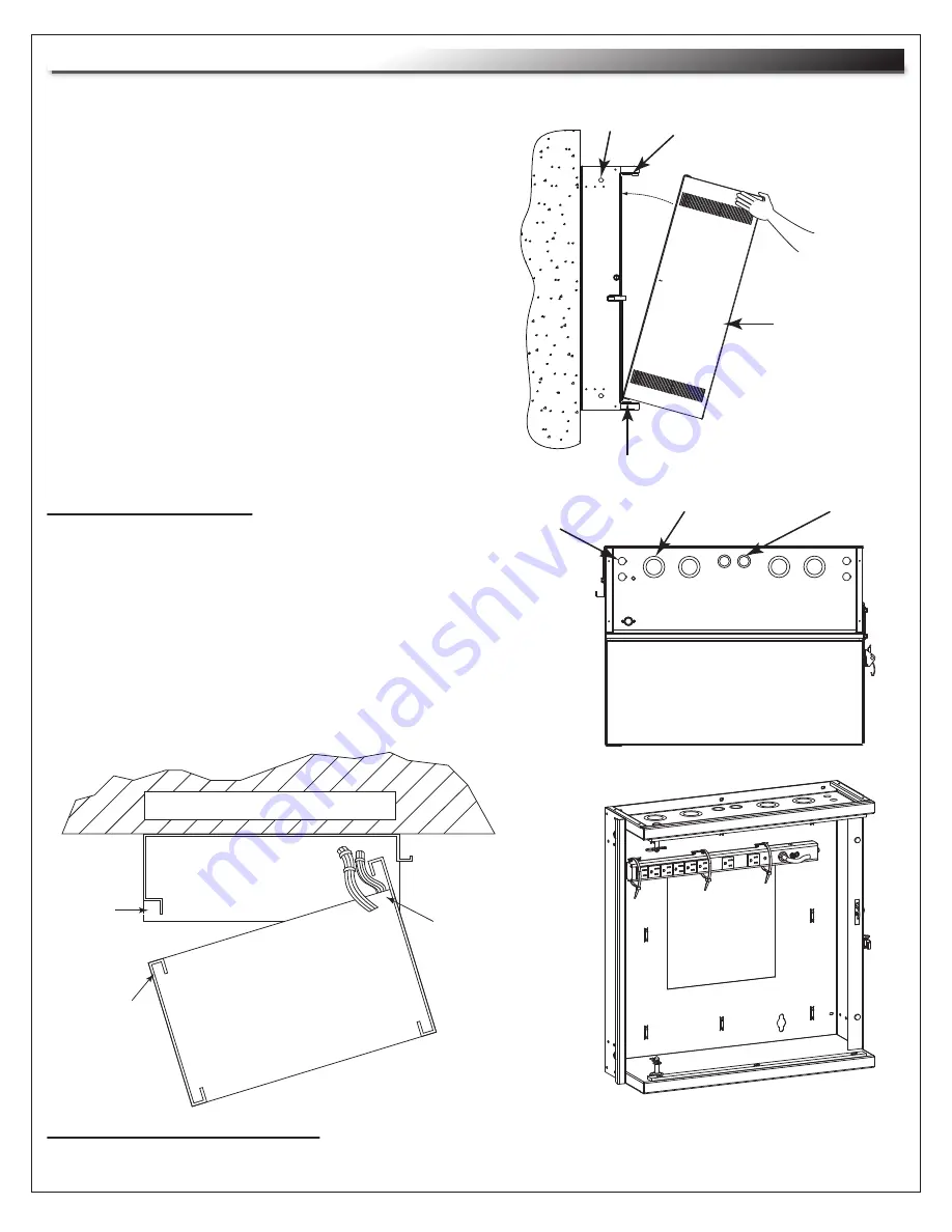
FIGURE D
PLACE HAND
HERE TO PIVOT
INTO PLACE
BACKPAN
Page 4
MOUNTING WALL
BACKPAN
PINCH
POINT
DO NOT
DRESS
WIRES ON
THIS SIDE
DRESS WIRES
AS SHOWN
ON PIVOT SIDE
CABLE MANAGEMENT
1" AND 1-1/2" EKO 1/2" AND 3/4" EKO
UHF/VHF ANTENNA
KO 5/8"
TOP VIEW
6) Align bottom of center section with lower
pivot bushing on backpan.
(FIGURE D)
7) Pivot top of center section into backpan and
align with upper pivot bushing.
(FIGURE D)
8) Insert pivot pin into upper bushing, hand tighten
fully and then back out one turn. Repeat for lower
bushing.
9) Install the security clips to prevent removal of pivot
pins from exterior of enclosure.
(FIGURE A)
FIGURE D
CENTER
SECTION
• Slots are provided on top and bottom of center
section for hook and loop.
• Bridge lances are provided on backpan for cable
management.
• 10-1/2" x 10-1/2" opening in the center of the backpan
for large electrical boxes.
(FIGURE X)
• Knockouts are provided in the top/bottom for electrical
fittings, UHF/VHF antennae & cable entry.
UPPER PIVOT BUSHING
UPPER PIVOT BUSHING
POWER STRIP INSTALLATION
NOTE:
For mounting PD-815SC / PD-815SC-NS Slim Power Strip, wire tie to bridge lances.
(FIGURE D)
CENTER
SECTION
INSTALLATION (Continued)


