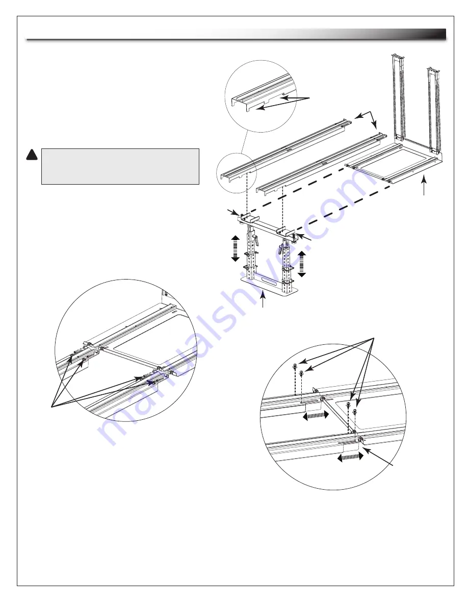
Middle Atlantic Products AX-SX Instruction Sheet Download Page 12

Hex Head

Screws

(2 Per Track)

10-32

Slide Support Screws

(2 Per Track)

SERVICE STAND / SERVICE TRACK ASSEMBLY

Page 12 

1) Assemble service stand as per instructions

  included with unit.

2) Adjust stand to approximate height of

  rough-in pan. 

(FIGURE H)

3) Position notched end of each service track on

  service stand saddles. 

(FIGURE H)

   CAUTION! 

Be sure notched ends are

    fully seated in service stand saddles

    to prevent tracks from falling out.

4) Position opposite end of each service

  track on millwork. 

(FIGURE H)

5) Secure each service track to rough-in 

  pan using (2) 10-32 hex head

  screws (included in service

  track hardware kit).

 (FIGURE I)

Notches

Saddle

Service

Stand

Service

Tracks

Saddle

Rough-in

Pan

FIGURE H

6) Fine adjust the service stand with

  the aid of the level installed in the

  service tracks.

7) Extend slide supports on each service

  track to meet millwork using slide

  support screws (2 per service track).

  (FIGURE J)


NOTE:

 This adjustment strengthens track when extending heavy equipment for servicing.

FIGURE I

FIGURE J

Slide

Support

!

Summary of Contents for AX-SX

Page 1: ...able service tracks Detachable rack frame allows off site equipment integration Articulating cable carriers attach to rack frame for effective cable management Rolling rack frame retracts into millwor...

Page 2: ...rough opening and base 2 Assemble frame 3 Install cable carriers rough in pan 4 Install service stand 5 Attach frame to tracks and cable carriers 6 Assemble leash 7 Tie cable to carriers 8 Secure rack...

Page 3: ...MES DURING THE ASSEMBLY OF THIS PRODUCT USE PROPER SAFETY EQUIPMENT AND TOOLS FOR THE ASSEMBLY PROCEDURE TO PREVENT PERSONAL INJURY CAUTION A CAUTION ALERTS YOU TO A SITUATION THAT MAY RESULT IN MINOR...

Page 4: ...bly 7 Rough In Pan Assembly Continued 8 Rack Assembly 9 Rack Assembly Continued 10 Rack Assembly Continued 11 Service Stand Service Track Assembly 12 Rack and Cable Carrier Installation 13 Cable Manag...

Page 5: ...ximum 17 for use with AX SX SSAX 28 for use with AXS SAX AXS xx 26 1 2 min set back 2 1 2 max TRACK25 24 1 2 max TRACK50 49 1 2 max NOTE Total rack height including rough in pan is the usable rack hei...

Page 6: ...6 53 11 16 55 7 16 57 3 16 58 15 16 60 11 16 62 7 16 64 3 16 65 15 16 67 11 16 69 7 16 71 3 16 72 15 16 74 11 16 76 7 16 78 3 16 79 15 16 10 11 12 13 14 15 16 17 18 19 20 21 22 23 24 25 26 27 28 29 30...

Page 7: ...e operation of this product to prevent the system from tipping and sliding off of tracks Failure to install cable carriers can result in serious damage to equipment and or risk of injury Rear Flange C...

Page 8: ...y into millwork mounting platform and mount with appropriate customer supplied hardware FIGURE B NOTE Refer to MILLWORK SPECS on page 5 for specific front setback dimensions Mounting Locations Mountin...

Page 9: ...om frame using 2 5 16 flange nuts per frame FIGURE C Mounting Studs 4 Per Rackrail 5 16 Flange Nuts 4 Per Rackrail Rackrail Top Frame Bottom Frame FIGURE C 1 Construct rough opening and base 2 Assembl...

Page 10: ...panels at the mid point of rackrail assembly FIGURE D FIGURE D Squaring Panels 2 Hex Head Screws 10 32 4 Per Rackrail Screws 10 32 4 Per Squaring Panel Top Frame Bottom Frame Rackrail 1 Construct roug...

Page 11: ...32 2 Per Squaring Panel Support Brackets 2 Included with larger racks Top Trim Panel Phillips Head Screws 2 10 32 x 1 4 6 Lay assembly on a flat level surface and square frame on all four corners FIG...

Page 12: ...from falling out 4 Position opposite end of each service track on millwork FIGURE H 5 Secure each service track to rough in pan using 2 10 32 hex head screws included in service track hardware kit FI...

Page 13: ...rew 1 10 32 x 5 8 CAUTION Do not allow the frame to roll off end of tracks RACK AND CABLE CARRIER INSTALLATION Page 13 2 Extend and secure each cable carrier to frame using 2 10 32 hex head screws inc...

Page 14: ...red directly to the millwork wherever a blank panel is located With rack closed remove blank panel and install customer supplied screws through each side of front rackrail into millwork FIGURE O FIGUR...

Page 15: ...rackrail and continue adhering across top and down to opposite side of rack 5 Trim excess length CLEAN ALONG THESE SURFACES GASKET ALIGN GASKET TO EDGE OF FLAT SURFACE 1 Remove dust and debris from r...

Page 16: ...HER WARRANTIES OF ANY KIND EITHER EXPRESSED OR IMPLIED INCLUDING BUT NOT LIMITED TO IMPLIED WARRANTIES OF MERCHANTABILITY AND FITNESS FOR A PARTICULAR PURPOSE TO THE MAXIMUM EXTENT PERMITTED BY APPLIC...

Reviews: