


The VCA and automute assignments are made using the assign keys.
The automation system must be unlocked and the correct assign mode selected (VCA or Mute). See
the automation section in this manual for more information.
To add a mute or VCA assignment, the desired assign keys should be selected. Normally pressing an
assign key will deselect the previous one. Should more than one key be desired, a long press of the
desired key will select the additional key without cancelling the previous selection.
To complete the assignment, select the channel to be assigned to the VCA or automute (see below).
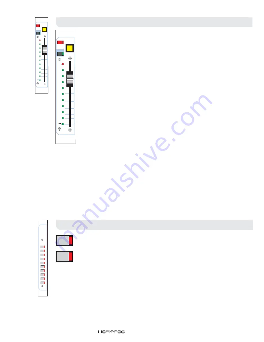
VCA Master Fader
VCA Master Fader
VCA Assign Keys
VCA Assign Keys
vca
master
fader
vca
assi
gn
k
eys
The VCA Master Fader panel contains ten (10) long-throw assignable VCA Faders. The Heritage
4000’s input channels may be assigned to any of the ten VCA’s. The Auxtender and Assignable Buss
Outs may be assigned to VCA’s 9 and 10 only.
- The VCA mute switch acts on any post fader input channel or sub-group that is assigned to
be controlled from the corresponding VCA master.
The mute can also be controlled by the snapshot automation system.
- When depressed, the VCA is removed from snapshot automation control over the
VCA fader and VCA mutes.
- The VCA solo switches are used to monitor the VCA faders by creating a mix of all the
inputs and sub-groups assigned to that VCA fader and routing the signal to the solo busses.
If the VCA solo is pressed in briefly, the solo will latch on or off. If the solo is pressed in for more than
one second then the latch is cancelled and the solo will be cancelled as soon as the switch is
released.
When the console is in solo ADD mode, input channels take priority over VCA fader solos.
- The fader adjusts the effective output level provided by the VCA continuously from off (-inf)
to +10dB.
The eleven (11) LEDs adjacent to the fader have a number of purposes depending upon the mode of
the automation system:
- All the status LEDs are off.
In this mode, the status LEDs are used to prompt the operator where to move the fader. When the fader is not at
the position stored in the current snapshot one or two LEDs will flash to indicate it’s preset position. A single
flashing LED indicates that the fader should be brought to this position. Two flashing LEDs indicate that the fader
should be positioned between the two. As the fader is moved towards the desired position the LED will light
continuously. Once the fader is in the correct position all LEDs will be extinguished.
When a scene’s contents are being checked (see the automation section) the status LEDs will indicate the fader
position by illuminating one or two LEDs as described above.
When in virtual fader mode (see the automation section), the atomation system generated a ‘virtual’ fader, set to
the level of the fader at the time the snapshot was stored. The status LEDs will display the level of the fader by
illuminating all the LEDs from -inf to the position of the ‘virtual’ faderA
MUTE
AUTO (Safe)
VCA Solo
Fader
Status LEDs
When in VCA or Mute Assignment Mode
Fader Manual Recall and NULL
Fader Position Check
Virtual Fader Recall
assign
keys
1
2
3
4
5
6
7
8
9
10
1
2
solo
10
10
5
5
0
20
30
40
50
dB
safe
MUTE
AUTO
solo
10
10
5
5
0
20
30
40
50
dB
safe
MUTE
AUTO
Operators Manual
- Page 21
Summary of Contents for HERITAGE 4000
Page 2: ......
Page 4: ......
Page 6: ......
Page 9: ...Mono Input Module Operators Manual Page 4...
Page 15: ...Stereo Input Module Operators Manual Page 10...
Page 20: ......
Page 21: ...Auxtender Pod Operators Manual Page 16...
Page 24: ......
Page 25: ...VCA Master Fader Operators Manual Page 20...
Page 28: ......
Page 29: ...Group Output Module Operators Manual Page 24...
Page 32: ......
Page 33: ...Matrix Module Operators Manual Page 28...
Page 35: ...Master Output Module Operators Manual Page 30...
Page 38: ......
Page 39: ...Monitor Module Operators Manual Page 34...
Page 43: ...Console Automation Operators Manual Page 38...
Page 51: ...Automation Linking Walkthrough Operators Manual Page 46...
Page 59: ...Weights and Dimensions Operators Manual Page 54...
Page 62: ......
Page 63: ...Block Diagrams Operators Manual Page 58...
Page 71: ...Crib Sheet Operators Manual Page 66...
Page 73: ...Features and Specifications Operators Manual Page 68...
Page 77: ......
Page 78: ......


