


46
Set channel sampling mode
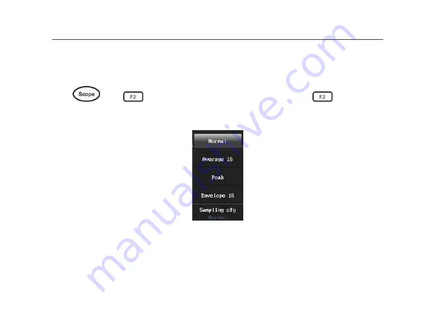
3.3 Set channel sampling mode
Press
and
to export sampling cfg menu, then press
and you can
choose the sampling config (user can operate the steps on touch screen). The sampling
config menu is shown in picture 3-4.
Picture 3-4 Sampling config menu
Systems can support four kinds of sampling configs
1.
Normal
oscilloscope samples signal through equivalent time intervals to build waveform,
Summary of Contents for MS300 Series
Page 13: ...Chapter One Safety Information Read First ...
Page 18: ...6 Oscilloscope quick start guide Chapter Two Oscilloscope Quick Start Guide ...
Page 36: ...24 General knowledge of users interface Picture 2 8 Users interface ...
Page 42: ...30 Understand touch screen Picture 2 10 touch area ...
Page 44: ...32 Function test Picture 2 11 Sine waveform 10V 50Hz ...
Page 47: ...35 Probe compensation Picture 2 14 Probe compensation connection ...
Page 49: ...37 Probe compensation Picture 2 18 Probe adjustment ...
Page 51: ...39 Chapter Three Use Oscilloscope ...
Page 79: ...67 Set store restore menu Picture 3 20 restore waveform ...
Page 84: ...72 Set store restore menu Picture 3 22 waveform data playback ...
Page 114: ...102 Set trigger menu Picture 3 38 Logic trigger ...
Page 118: ...106 Set trigger menu Picture 3 39 Standard PAL odd fields trigger ...
Page 121: ...109 Use vertical and horizontal button Picture 3 40 Roll mode ...
Page 127: ...115 Use math menu Picture 3 42 Ch1 Ch2 math function ...
Page 135: ...Use 50 shortcut 123 Picture 3 49 After using 50 shortcut ...
Page 137: ...125 Use touch screen zoom waveform Picture 3 50 Magnify selection area ...
Page 138: ...Use touch screen zoom waveform 126 Picture 3 51 magnified waveform ...
Page 139: ...127 Chapter Four Serial Bus Trigger Decode ...
Page 150: ...138 UART RS232 RS422 RS485 bus trigger and decode Picture 4 5 UART graphic interface ...
Page 153: ...141 UART RS232 RS422 RS485 bus trigger and decode Picture 4 6 UART text interface ...
Page 160: ...148 LIN bus trigger and decode Picture 4 10 LIN text interface ...
Page 168: ...156 CAN bus trigger and decode Picture 4 14 CAN text interface ...
Page 170: ...158 CAN bus trigger and decode Picture 4 15 CAN decode statistics ...
Page 175: ...163 SPI bus trigger and decode Picture 4 18 SPI trigger graphic interface ...
Page 177: ...165 SPI bus trigger and decode Picture 4 19 SPI text interface ...
Page 186: ...174 I2C bus trigger and decode Picture 4 23 I2C text interface ...
Page 188: ...176 Chapter Five Application Examples ...
Page 192: ...180 Measure simple signal Picture 5 1 auto measure ...
Page 197: ...185 Capture single pulse signal Picture 5 3 Capture the single pulse signal ...
Page 199: ...187 Analysis the signal detail Picture 5 4 peak sampling cfg ...
Page 201: ...189 Analysis the signal detail Picture 5 5 average sampling ...
Page 205: ...193 Use math FFT Picture 5 7 FFT waveform ...
Page 206: ...194 Chapter Six Use Multimeter ...
Page 217: ...205 Chapter Seven Use Recorder ...
Page 218: ...206 Use record This chapter mainly includes the below contents Start recorder Record Playback ...
Page 224: ...212 Record Picture 7 3 multimeter record ...
Page 242: ...230 Playback Picture 7 10 oscilloscope measurement record replays ...
Page 244: ...232 Playback Picture 7 11 oscilloscope waveform record replays ...
Page 246: ...234 Chapter Eight Users section ...
Page 252: ...240 Tools Picture 8 4 calculator ...
Page 259: ...247 Peference set Picture 8 9 preference set ...
Page 260: ...248 Chapter Nine ScopeSuite Software ...
Page 262: ...250 Chapter Ten Troubleshooting ...
Page 266: ...254 Index Chapter Eleven Services and Support ...
Page 270: ...258 Index Appendix ...
Page 296: ...Index 284 ...


