


Interfaces 6
miriac EK-5744 User Manual
V 1.2
39/53
© MicroSys Electronics GmbH 2017
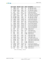
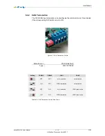
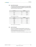
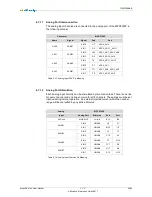
6.5.2 Input CPU Connection
For a correct input read sequence, the common stimuli pins for all inputs LDINA#
and LDINB# as well as the pins HDIN0# to HDIN3# for the corresponding inputs 0
to 3 must be actively set to a high level. A settling time of at least 100us must have
elapsed, before a valid read can be performed.
Digital Input
MPC5744P
Pin
Name
XDIN0
A11
Port E13
XDIN1
C9
Port H11
XDIN2
B13
Port H9
XDIN3
P17
Port D11
Table 6-8: Digital Inputs Pin Mapping
Stimuli
MPC5744P
Low active
Pin
Name
HDIN0#
K4
Port I8
HDIN1#
P5
Port I12
HDIN2#
M3
Port I10
HDIN3#
N15
Port I5
LDINA#
B4
Port D2
LDINB#
A5
Port D3
Table 6-9: Digital Inputs Stimulus Pin Mapping
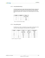
6.5.3 Input Test Feature
Each input can be fully tested during normal operation. The test will not be
disturbed by any input state or state change within the given nominal input limits.
The test will overwrite the current input information, so the user must take care
about the system functionality during the test sequence.
A valid input state can only be read if all input test stimuli are disabled for this input.


