background image


LEDs 8 


miriac SBC-LS1043A2 User Manual 

V 2.2 

64/72 


© MicroSys Electronics GmbH 2017 


LEDs 

8.1 

RJ45 LEDs 


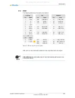
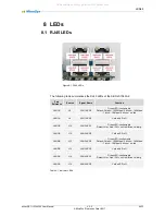
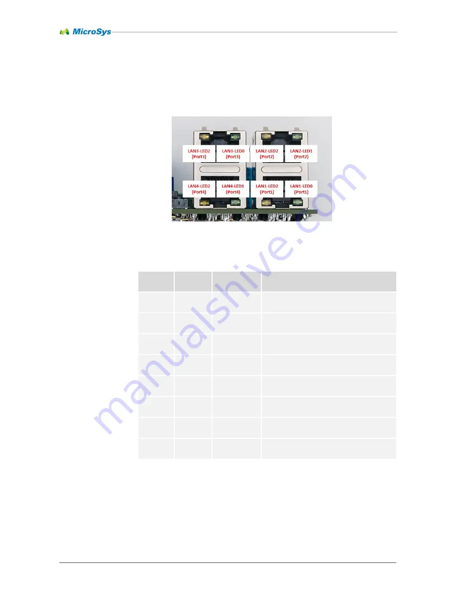
The following table summarizes the RJ45 LEDs of the SBC-LS1043A2: 

Part  

Reference 

Source 

Signal Name 

Function 

LAN1-A 

J8 

LAN1-LED0 

Green LED: configurable 

Default: 3 blinks 

– 1000Mbps / 2 blinks – 100 Mbps 

/ 1 blink 

– 10 Mbps / 0 blinks – no link 

LAN1-A 

J8 

LAN1-LED2 

Yellow LED: off 

LAN1-B 

J10 

LAN2-LED1 

Green LED: configurable 

Default: On = Link / Off = no Link / Blink = Activity 

LAN1-B 

J10 

LAN2-LED2 

Yellow LED: off 

LAN2-B 

J12 

LAN3-LED0 

Green LED: configurable 

Default: 3 blinks 

– 1000Mbps / 2 blinks – 100 Mbps 

/ 1 blink 

– 10 Mbps / 0 blinks – no link 

LAN2-B 

J12 

LAN3-LED2 

Yellow LED: off 

LAN2-A 

J14 

LAN4-LED1 

Green LED: configurable 

Default: On = Link / Off = no Link / Blink = Activity 

LAN2-A 

J14 

LAN4-LED2 

Yellow LED: off 

Table 8-1


Indicator LEDs 


Figure 8-1 RJ 45 LEDs 

All manuals and user guides at all-guides.com

Summary of Contents for miriac SBC-LS1043A2

Page 1: ...miriac SBC LS1043A2 User Manual CRX05 Revision 2 V 2 2 All manuals and user guides at all guides com a l l g u i d e s c o m...

Page 2: ...Current Measurement 23 4 6 6 Fuses 23 5 System Core Boot Configuration and On Board Memory 24 5 1 Processor NXP LS1043A 24 5 2 Nomenclature 24 5 3 JTAG Chain 24 5 4 Reset Structure 24 5 5 Clock Distr...

Page 3: ...3 72 MicroSys Electronics GmbH 2017 9 3 Flash Layout 68 9 3 1 NAND Flash 68 9 3 2 SD Card 68 9 3 3 QSPI Flash 68 10 Appendix 69 10 1 Acronyms 69 10 2 Table of Figures 70 10 3 Table of Tables 70 11 Hi...

Page 4: ...ent MicroSys Electronics GmbH neither gives any guarantee nor accepts any liability whatsoever for consequential damages resulting from the use of this manual or its associated product MicroSys Electr...

Page 5: ...pendent on the preferred carrier and the location where you want to have it shipped to by sending a request to MicroSys Electronics GmbH Muehlweg 1 D 82054 Sauerlach Germany In your request please pro...

Page 6: ...1 5 2 Conventions Symbol explanation denotes a low active signal denotes the signal flow in the shown direction denotes the signal flow in the shown direction denotes the signal flow in both direction...

Page 7: ...ring operation Take care not to touch any parts of the circuitry during operation to avoid burns and operate the unit in a well ventilated location Provide an appropriate cooling solution as required...

Page 8: ...respective MPX LS1043A2 SOM direct usage as an industrial computing solution This document gives you an overview on the board s connectors and how to take the first steps on the initial setup 2 3 Shi...

Page 9: ...nts of the CPU module consumption via I C current sense amplifier Added LAN interrupt support Added SMART CARD connector Added optional by assembly option extension connector for example for additiona...

Page 10: ...Ie SerDes 1 SGMII SerDes 2 SGMII SerDes 3 SGMII SerDes 4 mPCIe Aurora SerDes 5 PCIe SerDes 6 SATA SerDes 7 mPCIe mSATA RGMII 1 PHY USB 1 2 0 3 0 2 0 USB 2 2 0 3 0 2 0 SD Card 1bit 4 bit boot device UA...

Page 11: ...supply delivering 12V DC stabilized 2A minimum an USB cable type A mini B adapted to connector ST5 a serial terminal such as a PC with an USB port running a terminal Software e g TeraTerm HyperTermin...

Page 12: ...t the correct boot source and board configuration The board comes preconfigured to boot correctly on arrival Connect the mini USB cable to ST5 Connect other peripherals USB LAN SATA as far as intended...

Page 13: ...53 1600 MHz CPU1 A53 1600 MHz CPU2 A53 1600 MHz CPU3 A53 1600 MHz Bus 400 MHz DDR 1600 MT s FMAN 500 MHz Reset Configuration Word RCW 00000000 08100010 0a000000 00000000 00000000 00000010 33580002 000...

Page 14: ..._MDIO0 addr 2 Failed to connect Could not get PHY for FSL_MDIO0 addr 3 Failed to connect PCIe0 pcie 3400000 disabled PCIe1 pcie 3500000 Root Complex no link PCIe2 pcie 3600000 disabled FM1 DTSEC2 PRIM...

Page 15: ...to 4GByte up to 1600MT s 2 x DDR4 x16 single bank Synchronous Memory 8 bit NAND Flash Default 512 MB up to 2 GByte Hard Disk Drives Interface Not available PCI Express port 2 0 5Gbps Lane x1 Root com...

Page 16: ...IDT6V49205B Clock Generator TLC59116 RGB LED Driver MAX7325 GPIO Port Expander I2C 2 400 kbps Connected Devices SC18IS602BIPW I2C to SPI Bridge MAX9611AUB Current monitor TCA9544APWR I C Multiplexer G...

Page 17: ...l Dimensions 4 3 1 MPX LS1043A2 The following drawing shows the mechanical outline of the MPX LS1043A2 module that is plugged in the CRX05 carrier board This drawing is not to scale For 3D data files...

Page 18: ...ronics GmbH 2017 4 3 2 SBC LS1043A2 The following drawing shows the mechanical outline of the SBC LS1043A2 assembly This drawing is not to scale For 3D data files please contact MicroSys Figure 4 3 SB...

Page 19: ...System Description 4 miriac SBC LS1043A2 User Manual V 2 2 19 72 MicroSys Electronics GmbH 2017 4 4 Connector Layout Top Figure 4 4 Top connectors All manuals and user guides at all guides com...

Page 20: ...System Description 4 miriac SBC LS1043A2 User Manual V 2 2 20 72 MicroSys Electronics GmbH 2017 4 5 Connector Layout Bottom Figure 4 5 Bottom connectors All manuals and user guides at all guides com...

Page 21: ...values for the power supply This may result in severe permanent damage to the unit as well as possible serious injury 4 6 2 Input Power Connector Part Reference ST3 Manufacturer W rth Elektronik Type...

Page 22: ...he Power Supply structure 4 6 4 RTC Backup Battery The RTC on the module is supplied from a 470mF supercap that is loaded by the 5V power source on the carrier board Alternatively there s another vers...

Page 23: ...0m shunt resistor in the 5V path supplying the CPU module For automated measurements there s a carrierboard version available that already provides an I C current sense amplifier The current sense amp...

Page 24: ...CPU frequency can be clocked down if necessary 5 2 Nomenclature MicroSys Electronics GmbH developed a SoM called MPX LS1043A2 which is part of the SBC LS1043A2 evaluation kit It is based on the NXP LS...

Page 25: ...nal is not actively driven high by the carrierboard The RST IN is an input to the module It signals that the voltage supplies on the carrierboard are within their limits and no manual reset is trigger...

Page 26: ...anual V 2 2 26 72 MicroSys Electronics GmbH 2017 Voltage Monitoring Voltage Limit 3 3V Undervoltage Typ 2 925V 2 867V 2 984V 1 8V Undervoltage Typ 1 72V 1 69V 1 75V Table 5 2 Voltage monitoring limits...

Page 27: ...Pin Name Signal Pin Signal Pin P3 SDHC_CL K 10R LVL SHIFT SDC CLK B100 SDC CLK EMI 5 N1 IIC1_SCL I2C1 SCL B78 See chapter 5 9 1 K3 IIC2_SCL I2C2 SCL B75 See chapter 5 9 2 JTG0 E18 TCK JTCK B105 10R J...

Page 28: ...K1 AB8 26 PCIeT_LR1 SD1 REFCLK2 AB18 25 PCIeC_LR1 SD1 REFCLK2 AB19 ST4 J6 Signal Pin Signal Pin 36 PCIeT_LR4 SRD CLK1 T50 SRC 19 35 PCIeC_LR4 SRD CLK1 T51 SRC 20 ST7 OUT0 2 PCIE CLKD 13 OUT0 3 PCIE CL...

Page 29: ...ch have a default high state 10k pullups are on the module when no connection is made or SW1 is off When the switch is on the respective pin is grounded The BOOT SELx pins are decoded to the following...

Page 30: ...able 1 8V C6 CE IFC CS0 C17 IFC_CS0 chip select 1 8V D3 G4 H8 J6 VCC 1 8V C5 F7 K3 K8 GND GND 1 8V D5 CLE IFC CLE C19 IFC_CLE command latch enable 1 8V C4 ALE IFC AVD A18 IFC_AVD address latch enable...

Page 31: ...MB are available on request order The following table shows the internal connections I O Range QSPI Flash MT25QU128ABA8E12 LS1043A Pin Name Pin Name LVTTL C2 CS D8 QSPI_A_CS0 LVTTL B2 CLK C9 QSPI_A_SC...

Page 32: ...x55 Selectable via SW2 see 7 2 BR24G128NUX 3 EEPROM on carrier 0x58 MAX7325ATG Port Expander GP output address 0x68 Port Expander GP input address 0x60 TLC59116IRHBR RGB LED Driver Slave Address 0x68...

Page 33: ...49205B SCLK 46 SDATA 47 Module Connector I2C1_SCL B78 I2C1_SDA B77 MAX7325 SCL 19 SDA 20 BR24G128NUX 3 SCL 6 SDA 5 TLC59116IRHBR SCL 25 SDA 26 Table 5 8 I C 1 pin assignment 5 9 2 I2C 2 I C Bus 2 7 Bi...

Page 34: ...e I C multiplexer s channels The I C bus 2 has the following layout I O Range LVTTL Device SCL Signal Name Pin SDA Signal Name Pin LS1043A2 IIC2_SCL K3 IIC2_SDA L3 Module Connector I2C2_SCL B75 I2C2_S...

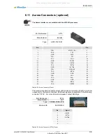
Page 35: ...ottom ST8 mPCIe slot Bottom ST9 PCIe extension connector Bottom ST10 SATA connector Top ST11 PCIe extension connector Bottom ST12 UART2 connector Top ST13 Aurora connector 1 Bottom ST14 Aurora connect...

Page 36: ...tributed over two connectors named LAN1 and LAN2 The connectors have integrated magnetics The following picture shows the front view of the two connectors as placed on the CRX05 baseboard For further...

Page 37: ...the reference voltage on pin T80 of the module connector ST4 as I O voltage 1 8V 88E1512P ST4 LS1043A Pin Name Pin Signal Pin Name 1 S_INP T41 SRD TX1 AD6 SD1 TX0 2 S_INN T42 SRD TX1 AE6 SD1 TX0 4 S_...

Page 38: ...ws the internal connections for Port 4 I O Range 88E1512P ST4 LS1043A Pull up Pull down Pin Name Pin Signal Pin Name 1 8V 46 RX_CLK T86 MII1 RXCK W1 MII_RX_CLK 1 8V 43 RX_CTRL T95 MII1 RXDV AB1 MII_RX...

Page 39: ...slot on the carrierboard The first one can hold mPCIe cards only mSATA is not supported The mPCIe slot is not connected on the SBC LS1043A2 and therefore can not be used It may be available in combina...

Page 40: ...Pin Pin 1 WAKE 3 3Vaux 2 3 COEX1 GND 4 5 COEX2 1 5V 6 7 CLKREQ UIM PWR 8 9 GND UIM DAT 10 11 REFCLK UIM CLK 12 13 REFCLK UIM RST 14 15 GND UIM VPP 16 MECHANICAL KEY 17 Reserved GND 18 19 Reserved WDIS...

Page 41: ...The following table shows the internal connections ST8 ST4 LS1043A2 Pin Name Pin Signal Pin Name 33 PET4 T23 SRD TX4 31 PET4 T24 SRD TX4 25 PER4 T20 SRD RX4 23 PER4 T21 SRD RX4 Table 6 9 mPCIe Slot S...

Page 42: ...Des configuration either mSATA or mPCIe cards can be used Part Reference ST7 Manufacturer Tyco Type 2041119 1 Used with Full size or half size mini PCIe or mSATA cards Four holes for broaching nuts ar...

Page 43: ...30 31 PET0 SMB DAT 32 33 PET0 GND 34 35 GND USB D 36 37 GND USB D 38 39 3 3Vaux GND 40 41 3 3Vaux LED WWAN 42 43 GND LED_WLAN 44 45 Reserved LED_WPAN 46 47 Reserved 1 5V 48 49 Reserved GND 50 51 Rese...

Page 44: ...ns pitch 0 5mm Pin 1 3 3V 2 3 3V 3 3 3V 4 1 5V 5 GND 6 REFCLK 7 REFCLK 8 GND 9 PER0 10 PER0 11 GND 12 PET0 13 PET0 14 GND 15 I2C2D SCL 16 I2C2D SDA 17 GND 18 PERST Table 6 12 PCIe Extension connector...

Page 45: ...ension connectors interface the CRX05 carrier board with any specially developed adapter No standard pinout is used Part Reference ST11 Manufacturer W rth Elektronik Type 687 118 140 22 Mates with FFC...

Page 46: ...l connections ST11 ST4 LS1043A2 Pin Name Pin Signal Pin Name 13 PET0 T17 SRD TX5 AD16 SD2 TX1_P 12 PET0 T18 SRD TX5 AE16 SD2 TX1_N 10 PER0 T14 SRD RX5 AG16 SD2 RX1_P 9 PER0 T15 SRD RX5 AH16 SD2 RX1_N...

Page 47: ...Part Reference ST10 Manufacturer 3M Type 5607 4200 SH Used with SATA cable 7pin The following table shows the internal connections ST10 ST4 LS1043A2 Pin Name Pin Signal Pin Name 1 GND 2 A T11 SRD TX6...

Page 48: ...ST1 ST4 LS1043A Pin Name Pin Signal Pin Name LVTTL 1 DAT2 B96 SDC D2 R1 SDHC_DAT2 LVTTL 2 CD DAT3 B95 SDC D3 T1 SDHC_DAT3 LVTTL 3 CMD B99 SDC CMD P2 SDHC_CMD 4 Vdd LVTTL 5 CLK B100 SDC CLK P3 SDHC_CLK...

Page 49: ...s B133 USB1 VBUS E7 USB1_VBUS 2 D T131 USB1 D E6 USB1_D_M 3 D T130 USB1 D F6 USB1_D_P 4 GND 5 SSRX T118 USB1 SSRX E3 USB1_RX_P 6 SSRX T119 USB1 SSRX E4 USB1_RX_M 7 GND 8 SSTX T122 USB1 SSTX F2 USB1_TX...

Page 50: ...SRX C3 USB2_RX_P 6 SSRX T113 USB2 SSRX C4 USB2_RX_M 7 GND 8 SSTX T116 USB2 SSTX D2 USB2_TX_M 9 SSTX T115 USB2 SSTX D1 USB2_TX_P J5 Pin Signal 4 ENABLE B127 USB2 EN L4 USB2_DRVVBUS 3 FAULT B126 USB2 OC...

Page 51: ...g port of the LS1043A Part Reference ST5 Manufacturer W rth Elektronik Type 651 005 161 21 Used with Mini USB type B cables The following table shows the internal connections ST5 ST4 LS1043A Pin Signa...

Page 52: ...O range is LVTTL For RS232 or RS485 additional transceivers are necessary They are not implemented on the SBC LS1043A2 system Part Reference ST12 Manufacturer W rth Elektronik Type 648 106 131 822 Ma...

Page 53: ...7 6 9 MCU Connector The connector MCU is for production test only Part Reference MCU Manufacturer Tag Connect Type TC2050 IDC FP MCU Pin Signal 1 Please contact MicroSys 2 3 4 5 6 7 8 9 10 Table 6 22...

Page 54: ...nufacturer Tag Connect Type TC2050 IDC FP JTG0 ST4 LS1043A Pin Signal Pin Signal Pin Signal 1 JTMS B102 JTMS G18 TMS 2 HRST B111 HRST F8 HRESET 3 1 8V 4 TRST B106 TRST E19 TRST 5 JTDO B104 JTDO E20 TD...

Page 55: ...19 TX3 GEN_IO3 20 21 TX3 RST 22 23 GND GND 24 25 TX4 CLK 26 27 TX4 CLK 28 29 GND GND 30 31 TX5 RDY 32 33 TX5 HRST 34 Table 6 24 Aurora Connector Pinout The module standard connector pinout ST4 does n...

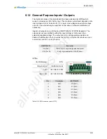
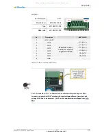
Page 56: ...output pins are level shifted to either the input voltage or to the level of an externally supplied voltage The output driver can be separately enabled and disabled Additionally a fault pin exists th...

Page 57: ...t on all ports together 350mA O13 Pin15 3 OUT5 O12 Pin14 4 OUT4 O11 Pin13 5 OUT3 O10 Pin12 6 OUT2 O9 Pin11 7 OUT1 O8 Pin10 8 GND Table 6 27 GPOUT connector pinout ST17 Pin 1 of connector ST17 is conne...

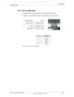
Page 58: ...rovides a fan connector marked with PWE In case a fan is necessary MicroSys recommends to use a 5V rated fan Part Reference PWE Manufacturer W rth Elektronik Type 679 304 124 022 Mates with 648 004 11...

Page 59: ...NOT CONNECTED TO THE LS1043A CPU Part Reference ST2 Manufacturer W rth Elektronik Type 693 022 010 811 Mates with t b d ST2 ST4 LS1043A Pin Signal Name Pin Description Pin Signal Name 1 3 3V 2 RST B67...

Page 60: ...ST18 Manufacturer W rth Elektronik Type 613 005 211 21 Mates with Standard 2 54mm dual row socket Pin Signal Name Connection 1 SEL_OUT MAX7325ATG O15 Pin17 2 MOSI SC18IS602BIPW MOSI Pin6 3 MISO SC18IS...

Page 61: ...low grounded The following table shows the internal connections of the BOOT SEL pins SW1 ST4 Microcontroller Switch Signal Pin Signal Pin Name 1 1 BOOT SEL1 T134 BOOT SEL1 61 PTD4 1 2 BOOT SEL2 T133 B...

Page 62: ...ration switch influences the behavior of the watchdog and the I C address of the EEPROM on I C Bus1 Setting SW 2 1 SW 2 2 Description OFF Watchdog disabled ON Watchdog active OFF EEPROM J25 address 0x...

Page 63: ...et input of a MAX6751KA29 chip via additional logic The resulting open drain reset signal is then inverted and fed to the microcontroller The following table shows the internal connections SW3 J17 ST4...

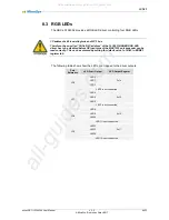
Page 64: ...LAN1 A J8 LAN1 LED2 Yellow LED off LAN1 B J10 LAN2 LED1 Green LED configurable Default On Link Off no Link Blink Activity LAN1 B J10 LAN2 LED2 Yellow LED off LAN2 B J12 LAN3 LED0 Green LED configurabl...

Page 65: ...tive LD3 J17 SW3 RST IN Power on the carrier is not ok watchdog reset is active manual reset is triggered Table 8 2 Indicator LEDs Carrier board Colour Function Green LED ON Power up sequence of the m...

Page 66: ...t pins of the MAX7325 port expander can be read correctly This can be achieved by setting the default value 1 of Bit 0 in MODE1 register to 0 The following table shows how the LEDs are mapped to the d...

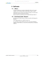
Page 67: ...card if both other boot options should fail for some reason Either boot option can be selected by the Boot Device Switch see chapter 7 9 2 Operating System Support MicroSys Electronics GmbH offers Li...

Page 68: ...d 1 block 512 byte Start block End block Definition 0000 0007 reserved 0008 2047 U boot 2048 2079 Environment 2080 2207 FMAN Microcode 2208 8191 reserved 8192 SDCARD SIZE 1 free Table 9 2 SD Card layo...

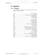
Page 69: ...Test Action Group LAN Local Area Network LED Light Emitting Diode LVTTL Low Voltage Transistor Transistor Logic MCU Microcontroller Unit MMC Multimedia Card mPCIe Mini Peripheral Component Interconne...

Page 70: ...autions 7 Table 2 2 Functional coverage 10 Table 4 1 Pinout ST3 21 Table 5 1 Reset signal overview 25 Table 5 2 Voltage monitoring limits carrier 26 Table 5 3 Clock distribution 28 Table 5 4 Hard wire...

Page 71: ...6 22 MCU Connector Pinout 53 Table 6 23 JTAG Connector Pinout 54 Table 6 24 Aurora Connector Pinout 55 Table 6 25 Aurora Connector ST14 Pinout 55 Table 6 26 GPIN connector pinout ST16 56 Table 6 27 GP...

Page 72: ...n Change Description 2017 10 06 2 0 Release Version for carrier CRX05 Revision 2 2017 11 09 2 1 Added I2C1 address 0x00 in Table 5 7 2018 07 16 2 2 Table 2 2 add LED colors Operating voltage change to...

Reviews:

Related manuals for miriac SBC-LS1043A2