System Core, Boot Configuration and On-Board Memory 5
miriac SBC-LS1043A2 User Manual
V 2.2
32/72
© MicroSys Electronics GmbH 2017
5.9
I²C Bus
The SBC-LS1043A2 offers two independent I²C busses.
The following tables show the I²C addresses as 7 Bit addresses. The R/W bit is not
displayed.
5.9.1 I2C-1
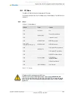
I²C Bus 1 (7-Bit address):
Address
Device
Function
0x32
RX-8803LC
RTC
0x00
TMP451AIDQF
General Call reset address
0x4C
Temperature sensor
0x50
BR24G128NUX-3
EEPROM (on module)
0x57 / (0x55)
Selectable via SW2 (see 7.2)
BR24G128NUX-3
EEPROM (on carrier)
0x58
MAX7325ATG
Port Expander GP output address
0x68
Port Expander GP input address
0x60
TLC59116IRHBR
RGB LED Driver Slave Address
0x68
All Call Address
(
must be disabled!)
0x6B
Software Reset Address
0x69
IDT6V49205BNLGI
Clock Generator
Table 5-7 I²C1 bus map
I²C address 0x68 is existing twice on I2C-1 bus.
Therefore, the so-
called “All Call I2C address” of the TLC59116IRHBR RGB LED
driver has to be disabled before GP input pins of the MAX7325 port expander can be
read correctly. This can be achieved by setting the default value 1 of Bit 0 in MODE1
register to 0.
All manuals and user guides at all-guides.com

