background image

4

Service Manual

   www.microphase.eu

Mini Dc

Description

Operation mode

General characteristic

Closing the velocity feedback loop to motor may be done in several different ways to accommodate
most applications. This types of velocity feedback are available with DC brush motors.

Velocity feedback

• DC motor with tachogenerator
• DC motor with internal PWM (Armature)
• DC motor with encoder

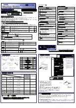
This is a drive capable to drive  

DC brush

 motors, up to 9Nm. It's a High Performance full four

quadrant drive servo amplifier. The mosfet output power stage is controlled by a 20 Khz PWM (Pulse
Width Modulation) signal that allows it to drive servo motors where high dynamic performance and
precise speed is required.

1.2

Operation mode and feedback

DESCRIPTION 

START INPUT 

Start  input,  enable  the  drive  with  range  from 
>9Vdc to +30Vdc (min/max)


STANDARD 

FAULT OUTPUT 

Fault drive, open collector output  100mA max. 
(Normally  closed,    opens    when  in  protection 
mode) 

STANDARD 

2 ANALOG 
OUTPUT 

1  motor  velocity  monitor  “V.TACHO”,  with 
range +/-8 Vdc output 
1  current  monitor  "I.MOTOR",  with  range  +/-8 
Vdc output 

STANDARD 

LED INDICATOR 

Four  LEDs  are  located  just  in  front  of  the 
potentiometers  and  show  the  current  state  of 
the drive 

STANDARD 


DESCRIPTION 

SPEED CONTROL 
INPUT 

It  is  speed  piloting  using  an  analogue 
reference (differential or common mode)


STANDARD 

TORQUE CONTROL 
INPUT 

It  is  torque  piloting  using  an  analogue 
reference.  This  function  allows  you  to  control 
the current from the drive. 

STANDARD 


Summary of Contents for Mini Dc

Page 1: ... Dc Series Precision Servodrive for DC Motors Service Manual MICROPHASE 36051 Creazzo Vicenza Italy Phone 39 0444 14 40 137 e mail info microphase eu MICROPHASE Eurocard Servodrive for Brush motors Servo Amplifier for Brush DC Motors Mini Dc ...

Page 2: ...urrent limitation TPRC 11 2 6 Ausiliary power supply 9 8V 11 2 7 Analog velocity input REF 12 2 8 Enable input START 12 2 9 Tachogenerator input 13 2 10 Current monitor output 13 2 11 Encoder inputs 13 Chapter 3 3 1 Internal adjustements 14 3 2 Adjustements with Tachogenerator feedback 15 3 3 Adjustements with Armature feedback 16 17 3 4 Adjustements with Encoder feedback 18 3 5 Current adjustment...

Page 3: ... the safety requirements may damage the equipment or injury the user This motion control equipment shoul be handled installed setted up and maintenanced only by competent personnel expert and trained in the installation of motion control electronic equipment Such technicians should be aware of potential electrical and mechanical hazards Shall never beliable or have any responsability if the produc...

Page 4: ...motors where high dynamic performance and precise speed is required 1 2 Operation mode and feedback DESCRIPTION START INPUT Start input enable the drive with range from 9Vdc to 30Vdc min max STANDARD FAULT OUTPUT Fault drive open collector output 100mA max Normally closed opens when in protection mode STANDARD 2 ANALOG OUTPUT 1 motor velocity monitor V TACHO with range 8 Vdc output 1 current monit...

Page 5: ... 1 3 View product 8 DS1 7 6 5 4 3 2 1 6 5 4 3 7 1 2 Mini 1 Product ID Label 2 Aluminum heatsink 3 Leds 4 Calibration Potentiometers 5 Test point V tacho I Motor GND 6 DIN 64 connector 32a 32c pitch 2 54 7 Adjustement zone 8 Adjustement settings ...

Page 6: ...rage temperature 10 70 C Drift analog input 0 5uV C Analog inputs REF 10Vdc max impedance 20Kohm cad Current monitor output I MOTOR 8Vdc Peak current Velocity monitor output V TACHO 8Vdc max velocity Power supply output 9 8V 9 8Vdc max 4mA Encoder max frequency 300Khz with level 2 8 24Vdc min max Fault drive output NPN 100mA max Start input Enable 9V 30Vdc min max Band width current 2KHz Band widt...

Page 7: ...ted in accordance to size See the table below Cable duct Conductive mounting panel zinc coated SIZE MODEL 3 6 4 8 7 14 10 20 14 28 20 40 65 N N N N N N2 145 N N N N N2 V 205 N N N N2 V V Positioning in the electrical box Follow the instructions in the positioning of the servodrive in the electrical box The drive is natural convection air flow cooled To ensure the drive cooling and make the install...

Page 8: ...ophase eu Mini Dc No Yes Mini Mini Mini 160 34 100 Mini Dimensions in mm Supplementary ventilation V Standard radiator fan cooling below the converter operating temperature 0 to 45 C Mounting position 1 7 Mechanical dimensions ...

Page 9: ... IN Reference Positive differential input Velocity command 7ac IN Positive drive enable with range 9Vdc min to 30Vdc max 8ac 10ac 12ac IN Programmable inputs 9ac IN Tachogenerator input 11ac OUT 4Vdc Rated current 8Vdc Peak current output in Volts This output may be used to monitor the torque the motor is producing 14ac 15ac 16ac 17ac IN Positive power supply HV voltage 19ac 20ac 21ac 22ac IN Nega...

Page 10: ...closed opens when the drive in protection mode With a voltage example from a CNC output you can command the drive in torque mode Applying a signal of 10V at TPRC the Drive to supply positive or negative peak current The formula to determine the value of Voltage to apply in TPRC in order to obtain requested current is the following Example Drive size 10 20A request current 8A NOTE In current refere...

Page 11: ...PRC a resistor 1 4W or 1 8W The figure is used a potentiometer With external resistance tends to zero ohms the output current tends to zero Increasing the ohmic value of resistance the value of current supplied increases With 47K of the current is limited to 50 on the Maximum size The loop motor speed remains active In the terminals 5ac 9 8V and 6ac 9 8V are available auxiliary supplies to power t...

Page 12: ...ode This analog in common mode has a 20Kohm of impedance input The following figure shows an application with speed reference connections using an internal 9 8V power supply The speed potentiometer must have an included value between 5 and 10Kohm Potentiometer 5K 10KOhm Is possible enable the drive connected the START input with 9 8V output terminal 5ac The standard drive is furnished in this conf...

Page 13: ...upplied by the drive For example if we have a size 7 14A 8V corresponds at 14A circulating on the motor The signal can be positive or negative depending on the direction of rotation of the motor In the terminals CHA and CHB on the rack or panel mounting can connect the inputs from an incremental encoder for the current feedback in response to encoder signals can come from encoder powered from 5 V ...

Page 14: ...he internal drive setting powering please wait at least 20 seconds after the power has been removed and the OK LED is off All of the personalizations are located inside of the DRIVE See figure above To gain access to the adjustment pads TOP DRIVE and the Dip DS1 BOTTON DRIVE DS1 SWITCH standard position are setting by factory for Tachogenerator feedback Ramp time disabled Standard Dynamic constant...

Page 15: ...e REF reference express in Volts To calculate RDT resistor please use the following formula Once the resistor RDT is inserted proceed with final speed adjustment Operate using trimmer SPEED on the front of the drive With Clockwise Rotation the speed increases With Counter Clockwise Rotation the speed decreases The Range of regulation is about 20 RDT resistor calculations In this configuration the ...

Page 16: ...components used to determine other calibrations for example Calibration current rating etc RA resistor calculations Vdc Vrms 1 41 EXAMPLE Brush DC motor with Ke 26V Krpm Vdc Drive model 145 Nominal speed N 3000rpm Risult Vdc 26 3000 1000 78V Insert on base RA to adapt the system to use the motor voltage Where For the Example risult Vdc 81V The table shows a resistor with a value of 33Kohm Once the...

Page 17: ...t a 470Kohm resistance If after insertion of the resistor the motor is unstable increase the Resistance value of RCA Where Vmot Nominal voltage of the motor Ri Max cold motor resistance Ipk Peak drive current Vref max applied reference voltage in REF Insert an RCA resistor on the header ajustement zone to compensate for voltage loss due to the motor resistance reducing the loss of RPM The formula ...

Page 18: ...0 or 22 Kohm Prefer resistance with 1 tolerance Once the resistor RENC is inserted proceed with final speed adjustment Operate using trimmer SPEED on the front of the drive With Clockwise Rotation the speed increases With Counter Clockwise Rotation the speed decreases The Range of regulation is about 20 Note The A and B signals may come from encoders powered by 5V to 24V The accepted logical level...

Page 19: ... 16 8 15 14 20 40 40 37 35 32 4 30 28 2 26 4 25 24 21 4 20 RIN resistor rated current adjustment Size drive A Rated Current request A RIP resistance limits the maximum current supplied by the converter For the calculation see the following table Resistance RIN limits the value of the rated current supplied by the drive Normally has the same value of the stall current of DC motor For the calculatio...

Page 20: ... SWITCH DS1 4 3 2 DS1 SWITCH ADJUSTEMENT PADS The product is standard setting with this feature is not enabled DS1 switch 2 and 3 OFF To enable the ramp acceleration close the DS1 switch 4 2 3 4 FUNCTION RANGE SETTING OFF OFF ON Ramp disabled NO SDT ON ON ON Ramp enabled 0 1 1sec Variable with ramp trimmer ON ON OFF Long ramp Insert RACC Variable with ramp trimmer RACC resistance value 820 Kohm 1 ...

Page 21: ...m 0 1 to 1 Sec with 10 V input velocity SPEED Motor fine speed calibration With rotating clockwise CW or counterclockwise CCW is possible increase decrease the speed of the motor with range 20 OFFSET Offset adjustment Allows the balance to zero motor speed Adjust this potentiometer to cancel any motor speed offset when the Velocity input is zero Max Velocity compensation 200mV PROP Gain potentiome...

Page 22: ...alibrations are performed using a reference speed in REF of about 1 or 2V You can use the voltage output from the CNC control paying attention to rule out the correction of space Or use an external oscillator or a small battery 1 5 V 3 8 Dynamic adjustement The multi turn PROP and DERIV trimmer allow to dynamically tune of the motor and its mechanics linked to it These trimmers have full excursion...

Page 23: ...tor goes out of control when enabled Encoder signals incorrectly connected ENC A and ENC B signals swapped or encoder power supply missing or tachogenerator signals swapped FUNCTION OK GREEN Normally ON Indicating the proper operation of all functions It turns OFF in case of any anomaly except protection intervention IxT The faults that affect this LED are Over Under input voltage Over temperature...

Page 24: ...24 Service Manual www microphase eu Mini Dc White page ...

Reviews: