


Publication date: August, 2012
Revision A1
48
•
4-1-1. The Information of Page Layout
On the top part of the information page, it shows the front panel of the switch.
Linked ports will be displayed in green color, and linked-off ones will be in black.
For the optional modules, the slots with no module will only show covered plates,
the other slots with installed modules would present modules. The images of
modules would depend on the ones you insert. Vice versa, if ports are
disconnected, they will show just in black.
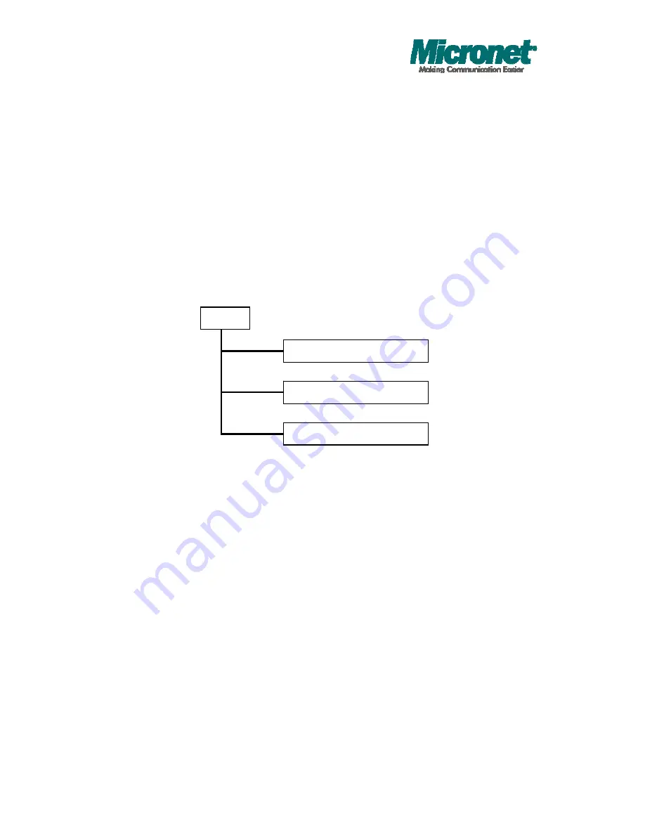
On the left side, the main menu tree for web is listed in the page. According to
the function name in boldface, all functions can be divided into three parts,
including “Configuration”, “Monitoring” and “Maintenance”. The functions of each
folder are described in its corresponded section respectively. As to the function
names in normal type are the sub-functions. When clicking it, the function is
performed. The following list is the main function tree for web user interface.
Configuration
Monitoring
Maintenance
Root
Summary of Contents for SP6524PWS
Page 1: ...User s Manual 20 port 10 100 1000M 4G Combo Web Smart PoE Switch Model No SP6524PWS ...
Page 66: ...Publication date August 2012 Revision A1 57 Fig 4 5 2 Per port configuration ...
Page 75: ...Publication date August 2012 Revision A1 66 Fig 4 12 Mirror ports configuration ...
Page 81: ...Publication date August 2012 Revision A1 72 Fig 4 15 Rate Limit Configuration ...


