1HW)5$0(6HULHV6HUYHU4XLFN6WDUW*XLGH
0LFURQ(OHFWURQLFV,QF
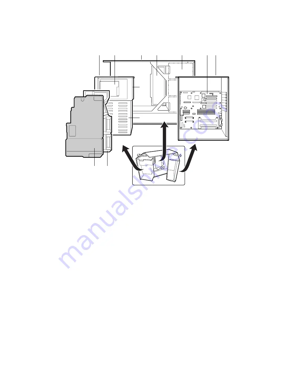
Chassis Side View
OM07715
I
H
D
A
B
C
E
F
G
K
J
Figure 3. Chassis Side View
A. Front swing-out subchassis
B. Diskette drive*
C. Main chassis
D. Power share board
E. Power supply(s)
F. Server board*
G. Lift-out electronics bay
H. Foam fan housing
I.
Foam fan housing cover
J.
SCSI hard drive bay
K. 5.25-inch device bay
* Items shown may not be included in the chassis.
Removing the Access Cover
You need to remove the access cover, and in some cases the front bezel, to reach components inside the
chassis. Facing the front of the chassis, the access cover is on the right side for pedestal-mounted (tower)
servers and on the top for rack-mounted servers.
1. Observe the safety and ESD precautions at the beginning of this chapter.
2. Turn off all peripheral devices connected to the server.
3. Turn power to the server OFF by using the power on / off switch on the front panel AND unplug all
AC power cords.
4. Label and disconnect all peripheral cables attached to the I/O panel.


