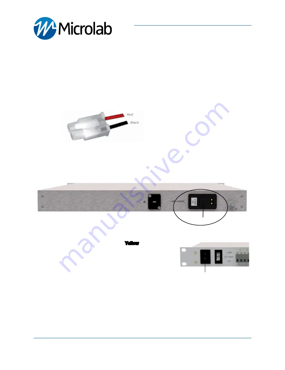
Power up Sequence:
Required:
• -48/+24VDC power source with the included power cable model
PSM-129
. Follow wiring diagram shown
1. Carefully align and mate the power cable DC connector to the Head-End unit’s
DC ONLY
power receptacle
2. Turn on DC power source and
Switch On
the unit
- Both Antenna Status LEDs will flash
Yellow
during bootup
- Wait 1 minute for device bootup
- Solid
GREEN
Antenna LEDs indicate normal operation
-
See
LED/Antenna Verification
section for details
- Off Status LEDs indicate that power supply is not functioning
or not connected.
Microlab, A Wireless Telecom Group Company, 25 Eastmans Road, Parsippany, NJ 07054
Tel: (973) 386-9696 • [email protected] • www.microlabtech.com • Fax: (973) 386-9191
Connecting Power
Connect DC Positive and Negative terminals as
follow:
1. Red
(Positive (+)/
Required
)
2. Black
(Negative (-)/
Required
)
Power Cable
Power
Switch
GPSS216 Quick Start Guide
Lossless GPS Signal Splitter, 16 RF Ouput
page 5
DC ONLY


