background image

GREER COMPANY

GREER COMPANY

GREER COMPANY

GREER COMPANY    


Crane Systems 

GREER COMPANY

 1918 EAST GLENWOOD PLACE, SANTA ANA, CA 92705  

PN W450250 Rev B 08/09/00 

RCI 510 RATED CAPACITY INDICATOR     OPERATOR'S MANUAL    

             TEL:(714) 259-9702 FAX:(714) 259-7626 


27 of 35 

OPERATOR SETTABLE ALARMS

OPERATOR SETTABLE ALARMS

OPERATOR SETTABLE ALARMS

OPERATOR SETTABLE ALARMS

 CONTINUED

 CONTINUED

 CONTINUED

 CONTINUED


ACCESSING SWING AND 

ACCESSING SWING AND 

ACCESSING SWING AND 

ACCESSING SWING AND     
WORK AREA ALARMS

WORK AREA ALARMS

WORK AREA ALARMS

WORK AREA ALARMS    

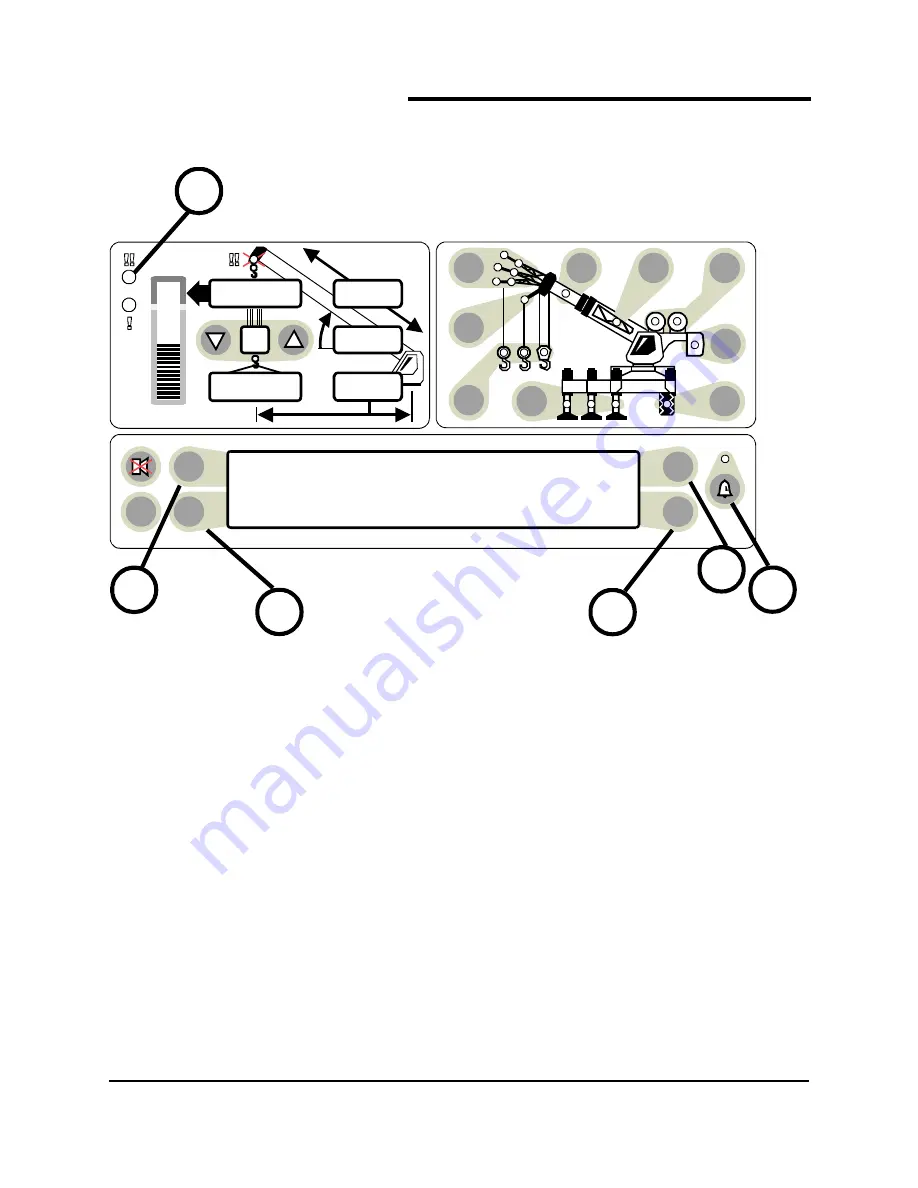
To access the SWING AND WORK AREA 
ALARMS from the main working screen, press 
the OPERATOR ALARM push button (item 24)  
2 times. 

The Information Screen will show the current 
status of the Swing and Work Area Alarms. 

There are 4 separate operator alarms, all 
controlled by push buttons (items 25, 27, 28, 
and 29). Each one of these push buttons relates 
to the alarm to which it points. 


Each push button operates as a toggle switch. If 
the alarm to be set is OFF, pressing the push 
button will turn the alarm ON. If the alarm to be 
set is ON pressing the push button will turn the 
alarm OFF. 

When Operator Alarms are set, the light in the 
push button (item 24) will be illuminated. 

Return to the main screen by pressing the 
OPERATOR ALARM push button (24). 


LEFT SWING OFF           RIGHT SWING OFF   

LEFT POINT OFF           RIGHT POINT OFF

TEST

MAX

SET

6

23,500

i2,300

44.8

62.7

26.4

24

25

5

29

28

27

Summary of Contents for RCI 510

Page 1: ...TOR OPERATOR S MANUAL TEL 714 259 9702 FAX 714 259 7626 1 of 35 M M M MI I I ICROGUARD CROGUARD CROGUARD CROGUARD RCI 510 RCI 510 RCI 510 RCI 510 TELESCOPIC BOOM CRANES OPER OPER OPER OPERA A A ATOR S...

Page 2: ...You The Pictograph 5 Information Screen 6 Parts of Line Indicator 6 Operator Alarms Indicator 6 Pre Alarm Indicator 6 Overload Indicator 6 Anti Two Block Indicator 6 Bar Graph for Percentage of Rated...

Page 3: ...ibs 15 Erected Jibs 16 Auxiliary Head 17 Choosing the Winch 18 Choosing the Point of Lift 19 Setting the Parts of Line 20 Notes 21 Cancel Alarm Push Button to Cancel Audible Alarm 22 Reset Function Ki...

Page 4: ...gle sensor is mounted inside the cable extension reel assembly EXTENSION SENSOR EXTENSION SENSOR EXTENSION SENSOR EXTENSION SENSOR The extension sensor provides an increasing voltage proportional to t...

Page 5: ...contain 3 LEDs These indicate the selection of either full outriggers intermediate or retracted outriggers TIRES contain 1 LED When operation on tires is selected the outrigger LED will turn off and t...

Page 6: ...parts of line currently selected 3 The OPERATOR ALARM lamp illuminates when operator alarms have been set 4 The PRE ALARM AMBER indicator illuminates at a preset value of 90 of Rated Capacity and pro...

Page 7: ...d slings etc suspended below the lifting point 9 The RATED CAPACITY display shows the RATED CAPACITY of the crane in the current configuration 10 The RADIUS display shows radius of the load Radius is...

Page 8: ...IFT e g main boom auxiliary head or jib 15 AUXILIARY HEAD ON or OFF the crane 16 Indicates JIB configuration in use 17 MANUAL SECTION or ACTIVE TIP extended if applicable 18 JIB STOWED ON BOOM 19 Indi...

Page 9: ...EST TEST TEST Immediately following electrical power up or following operation of the TEST switch item 26 the system executes a self test that last for 8 seconds During this time the numerical display...

Page 10: ...START UP SCREEN START UP SCREEN Immediately following power up self test the display indications will show as above During this time crane motions are disabled by the system function kickout Operation...

Page 11: ...htness and contrast control functions Push buttons to the left of the information display item 25 allow the brightness of all LED s on the display panel to be adjusted up or down at any time during op...

Page 12: ...CRANE On cranes that have counterweight options the operator must tell the MicroGuard System which counterweight is currently fitted If there are no options continue on to selection of outriggers Sta...

Page 13: ...which outrigger position is in use Start the choice by pressing the outrigger push button item 22 The outrigger selection will automatically move on to the next selection EXAMPLE From fully extended t...

Page 14: ...t corresponds to the tire chart to be used Start the choice by pressing the tire push button item 21 The available tire selection options will be displayed in the information screen item 1 There can b...

Page 15: ...R DETAILS OF THE OPTIONS ON YOUR CRANE On cranes that have more than one jib option fixed offset or telejib etc the operator must select the jib to be used Start the choice by pressing the stowed jib...

Page 16: ...UAL FOR DETAILS OF THE OPTIONS ON YOUR CRANE To erect a JIB it must first have been selected and stowed as detailed on the previous page Start the choice by pressing the erected jib push button item 1...

Page 17: ...F THE AUXILIARY HEAD PUSH BUTTON IS PRESSED ON A CRANE THAT DOES NOT HAVE AN AUXILIARY HEAD THE MESSAGE NO OTHER AUXILIARY HEAD OPTIONS WILL APPEAR IN THE INFORMATION SCREEN ITEM 1 An auxiliary head f...

Page 18: ...to be used for the lift before selecting the point of lift and parts of line The system stores point of lift and parts of line selections for each winch Choose the winch to be used by pressing the win...

Page 19: ...check the point of lift selection following selection of the winch Choose the point of lift to be either from the main boom auxiliary head or jib by pressing the point of lift push button item 14 This...

Page 20: ...ct parts of line following selection of the winch and point of lift Set the PARTS OF LINE for the currently selected winch by pressing the UP or DOWN arrow as appropriate item 13 The number of parts o...

Page 21: ...previously set After removing power to the system and then powering up again the settings remain intact until reset by the operator After the configuration has been set the operation of the System dep...

Page 22: ...ELING AN AUDIBLE ALARM If the audible alarm sounded because of an overload condition the alarm will remain canceled until the condition is corrected If another alarm condition occurs that normally cau...

Page 23: ...is necessary in this situation Press and release and then press and hold the CANCEL ALARM push button item 23 for approximately 5 seconds to reset the relay At this time a second beep is heard confir...

Page 24: ...umber identity of the push button that controls each alarm These buttons are called out in the illustration above Minimum Boom Angle item 28 Maximum Boom Angle item 29 Maximum Boom Length item 25 Maxi...

Page 25: ...splay will read MIN ANGLE 32 The red warning light item 5 will flash and the audible alarm will sound whenever the boom angle is below 32 Pressing the MIN ANGLE push button again will cancel the alarm...

Page 26: ...read MAX LENGTH 58 FT The red warning light item 5 will flash and the audible alarm will sound whenever the boom length exceeds 58 ft Pressing the MAX LENGTH push button again will cancel the alarm a...

Page 27: ...king screen press the OPERATOR ALARM push button item 24 2 times The Information Screen will show the current status of the Swing and Work Area Alarms There are 4 separate operator alarms all controll...

Page 28: ...activated when swinging to the left A right swing alarm is activated when swinging to the right In this example the working arc is the larger piece of the pie WORKING ARC AND EXCLUSION ZONE EXCLUSION...

Page 29: ...will read LEFT SWING 325 Both Left and Right Swing Alarms must be set for the system to operate correctly The red warning light item 5 will flash and the audible alarm will sound whenever only one of...

Page 30: ...a When passing the plane the red warning lamp will illuminate the audio alarm will sound and the message EXCLUSION ZONE will flash on the display OBSTACL E Set Point 1 Set Point 2 Operating Zone Opera...

Page 31: ...inting to Left Point The information screen item 1 will read LEFT POINT SET Both Left and Right Points must be set for the system to operate correctly The red warning light item 5 will flash and the a...

Page 32: ...head AUXILIARY HOIST AUX HOIST A separate hoist rope system other than the main hoist BARGRAPH A pictorial device used to illustrate quantitative relationships BOOM A member hinged to the upperstruct...

Page 33: ...of a boom FUNCTION KICK OUT A device that disengages certain crane functions whose movement could cause overload or two blocking HEIGHT The vertical distance from the ground to the tip of the boom or...

Page 34: ...f the hook RATED CAPACITY The lifting capacity of a crane as determined by the published capacity chart RATED CAPACITY The load that a crane can safely handle based on factors such as strength stabili...

Page 35: ...pacity which is being utilized at any one time expressed as a percentage of rated capacity TRANSDUCER A device that is actuated by energy from one system and converts this to another form for use by a...

Reviews: