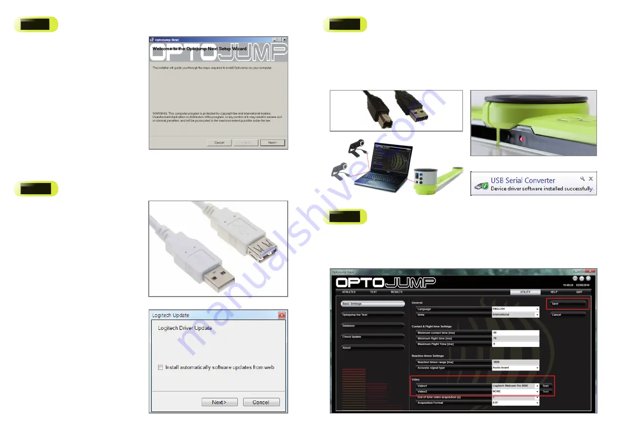
Install OptoJumpNext.exe
a.
Launch the executable fi le “OptoJump Next.Exe“
found on the Usb Key provided with the Kit, or
downloaded from
www.optojump.com
website;
b.
Follow the wizard (Fig. 1) by clicking “
Next>
”
until the software is completely installed;
c.DO NOT RUN
the software, until you perform
the steps 2 and 3.
Figure 3
Attach the webcam and install driver updates
a.
Attach the Logitech webcam to the PC’s USB port and
wait until the driver is completely installed. For longer
distance than 1,5 mt. please use the white USB
extension cable (Fig. 2);
b.
Next follow the wizard (Fig. 3) to download and
install the latest driver updates from Logitech
Website (an Internet connection is required);
c.
If you are not connected to Internet, uncheck the
fl ag “Install Updated” and close the wizard;
d.
Please note that if you attach a second webcam,
or if you change the USB port, the driver will be
re-installed and you’ll have to follow the same
procedure described above.
Attach the OptoJump Next Hardware
a.
Connect the black USB cable (Fig. 4) from the OptoJump Next RX Bar to the PC;
b.
Power on the system by toggling the switches on each bar. You should see near the power socket a green-fl ashing
LED indicating batteries are charged. In case the LED is red-fl ashing, connect the power (see par. 4.3 on user
manual);
c.
Align the TX and RX bars in front of each other (max 6 meters distance) until the LED status indicator positioned along the
RX bar (Fig. 5) become from “red” to “green“;
d.
Wait until the driver is successfully installed (Fig. 7) before moving to the next Step 4.
Figure 8
Launch the OptoJump Next Software and select the webcam
a.
Launch the software by double-clicking the OptoJump Next desktop icon;
b.
Choose the desired language and wait until the software is completely loaded;
c.
To select and test the webcam, click “Utility” on the Main Menu and then the “Basic Settings” button in the left column.
d.
In the Video Section, choose the
Logitech Webcam Pro 9000
from the dropdown menu and then click the “Test”
button (Fig.8);
Figure 6
Figure 7
Figure 5
Figure 4
Figure 1
Figure 2


