MM30-DK
Doc. N° MO-0050-ING
Rev.
2
Pag.
31
of
36
Copyright - 2010 - Microener
20. INVERSE TIME UNBALANCE PROTECTION ELEMENT (TU0248 Rev.1)
Page 1: ...r MICROPROCESSOR MOTOR PROTECTION RELAY WITH DIRECTIONAL EARTH FAULT ELEMENT TYPE MM30 DK OPERATION MANUAL MULTIFUNCTION MOTOR PROTECTION RELAY TYPE MM30 DK MODE SELECT T St No I Is 1 PROG I R F I ROT...
Page 2: ...on__________________________________________________________________________ 13 2 4 4 Operation during power off_________________________________________________________________ 13 2 4 5 Time toleranc...
Page 3: ...compatible with their declared performance 1 6 PROTECTION EARTHING When earthing is required carefully check its effectiveness 1 7 SETTING AND CALIBRATION Carefully check the proper setting of the dif...
Page 4: ...REPAIR Internal calibrations and components should not be altered or replaced For repair please ask the Manufacturer or its authorised Dealers Misapplication of the above warnings and instruction reli...
Page 5: ...he input Current Transformers and refers all its measurements to that value To make the relay properly working with any C T when programming the relay settings we have to input the value of the Rated...
Page 6: ...Phase to Earth Fault Same as A B D Three Phase Fault All the three currents are correctly measured in any case two directly 2 2 2 3 Earth Fault Current and Voltage Inputs The real time measurement of...
Page 7: ...current Ip preheating current Ib continuously admissible current 1 1 3 Im step 0 01Im Im motor rated current 0 1 1 5 In step 0 1In Steady motor cooling down time constant to 1 10 tm step 1tm The cool...
Page 8: ...ontrols another inverse time element Minimum Negative Sequence current operation level Is 0 1 0 8 Im step 0 1lm lf ls DIS the function is disactivated Time current curve tIs 1 8 s step 1s Actual trip...
Page 9: ...d for the time tI tBO After this delay the relay it is anyhow reset tBO 0 05 0 5 s step 0 05s 2 2 3 7 F64 Earth Fault protection Minimum Pick up Zero Sequence Residual Current level O 0 1 4 On step 0...
Page 10: ...inhibition is permanent until the RESET key is operated 2 2 3 9 Starting Sequence Control During start up of the motor the unit can control an output relay used to operate the switch over of motor sta...
Page 11: ...Motor rated current lm 0 1 1 5 In step 0 01In Motor starting current lst 0 5 9 9 Im step0 1 Im Starting time tst 1 120 s step 1s Transition current level ITr 0 11 Ist step 0 1 Ist Transition time tTr...
Page 12: ...s o o The relay measurement is 3Io x cos o o Io The relay trips 3Uo Uo when Io O fig 2 i e when the component of the input current in the measuring direction of the relay exceeds the set trip level Is...
Page 13: ...displayed with one of the groups of digits YY MMM or DD blinking The DOWN key operates as a cursor It moves through the groups of digits in the sequence YY MMM DD YY The UP key allows the user to mod...
Page 14: ...nning by the key SELECT Parameter modification by the key Set validation by the key ENTER Scanning of the menus by the key MODE SELECT ENTER Enabled only if input current is zero ENTER RESET MODE SELE...
Page 15: ...evel I Illuminated on trip after tI time delay g Red LED O Flashing when earth fault current exceeds the set level O Illuminated on trip after tO time delay h Yellow LED ROTOR STALL Illuminated on tri...
Page 16: ...and are controlled by the master module MM30 DKX via a screened twisted pair of cables connecting dedicated RS485 serial ports see diagram herebelow The module REX 8 includes eight RA RB RC RD RE RF...
Page 17: ...0 DK Doc N MO 0050 ING Rev 2 Pag 17 of 36 Copyright 2010 Microener Any of the functions featured by the MM30 DK can be programmed to control up to four out of the sixteen user programmable output rela...
Page 18: ...n be connected via a cable bus or with proper adapters a fiber optic bus for interfacing with a Personal Computer type IBM or compatible All the operations which can be performed locally for example r...
Page 19: ...D terminals 1 14 Thermal probe This function is enabled by programming the variable RTD ON see 12 1 If the function is enabled the input RTD is activated when the resistance connected to the terminals...
Page 20: ...memory SET DISP Reading of the settings and of the configuration of the output relays as programmed PROG Access to the programming of the settings and of relay configuration TEST PROG Access to the ma...
Page 21: ...ad current unbalance degree 0 999 Uo xxxxxV RMS Voltage displayed as primary volts 0 65000 o xxx Phase displacement h xxxxx Operation hours 0 65000 10 2 MAX VAL Highest values recorded during motor ru...
Page 22: ...ent Is mxxx Negative sequence component of current T Tnxxx Motor heating UoxxxxxV Zero sequence voltage oxxxxx Io Uo phase displacement angle in degrees 10 4 TRIP NUM Counters of the number of operati...
Page 23: ...SELECT now scrolls the available parameters By the key the displayed values can be modified to speed up parameter s variation press the key SELECT while or are pressed Press key ENTER RESET to validat...
Page 24: ...y of LR element during run 1 25 1 s Is 0 3Im Trip level of inverse time current unbalance protection element Dis 0 1 0 8 0 1 Im tIs 4s Trip time delay of inverse time current unbalance protection when...
Page 25: ...R4 RA RB RL StNo 1 Start No limitation tripping operates relay R1 R2 R3 R4 RA RB RL ILR 1 Locked Rotor tripping operates relay R1 R2 R3 R4 RA RB RL tI2 1 Time delayed unbalance tripping operates rela...
Page 26: ...s generally recommended that this test be run only in a bench test environment or after all dangerous output connections are removed 14 MAINTENANCE No maintenance is required Periodically a functional...
Page 27: ...EC61000 4 4 level 3 2kV 5kHz HF disturbance test with damped oscillatory wave 1MHz burst test IEC60255 22 1 class 3 400pps 2 5kV m c 1kV d m Oscillatory waves Ring waves IEC61000 4 12 level 4 4kV c m...
Page 28: ...MM30 DK Doc N MO 0050 ING Rev 2 Pag 28 of 36 Copyright 2010 Microener 16 CONNECTION DIAGRAM SCE1495 Rev 2 Standard Output 16 1 CONNECTION DIAGRAM SCE1756 Rev 0 Double Output...
Page 29: ...MM30 DK Doc N MO 0050 ING Rev 2 Pag 29 of 36 Copyright 2010 Microener 17 WIRING THE SERIAL COMMUNICATION BUS SCE1309 Rev 0 18 CHANGE PHASE CURRENT RATED INPUT 1 OR 5A...
Page 30: ...MM30 DK Doc N MO 0050 ING Rev 2 Pag 30 of 36 Copyright 2010 Microener 19 THERMAL IMAGE CURVES TU0249 Rev 1...
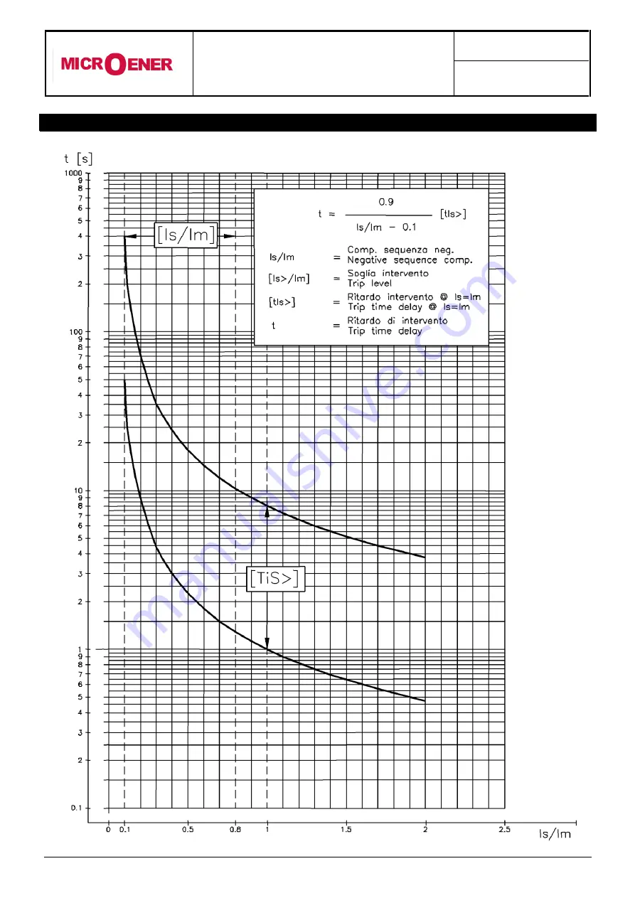
Page 31: ...MM30 DK Doc N MO 0050 ING Rev 2 Pag 31 of 36 Copyright 2010 Microener 20 INVERSE TIME UNBALANCE PROTECTION ELEMENT TU0248 Rev 1...
Page 32: ...of the screws driver mark Draw out the PCB by pulling on the handle 21 2 Plug in Rotate clockwise the screws and in the horizontal position of the screws driver mark Slide in the card on the rails pro...
Page 33: ...MM30 DK Doc N MO 0050 ING Rev 2 Pag 33 of 36 Copyright 2010 Microener 22 OVERALL DIMENSIONS MOUNTING...
Page 34: ...MM30 DK Doc N MO 0050 ING Rev 2 Pag 34 of 36 Copyright 2010 Microener 23 KEYBOARD OPERATIONAL DIAGRAM...
Page 35: ...nstant 3 1 10 Ta n Prealarm motor heating level 90 50 110 Ts n Motor restart heating level 100 40 100 Ib Rated maximum continuous motor overload 1 05 Im 1 1 3 StNo Max No of startings allowed within t...
Page 36: ...Starting switch over tripping ITr StNo 1 Start No limitation tripping StNo ILR 1 Locked Rotor tripping ILR tI2 1 Time delayed unbalance tripping tI2 I No load running tripping I I Instantaneous overcu...