


IIn
nttrro
od
du
uccttiio
on
n
MicroE Systems was founded to advance encoder technology to
a level never before achieved. Our objective was to design encoder
systems that would be small enough to fit into densely packed OEM
equipment designs, affordable enough for cost-sensitive applications
and easy enough to enable installation, setup and alignment by
assemblers with little training. We are pleased to say that all of
these goals have been realized with the introduction of the Mercury
family of encoders.
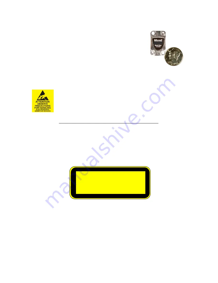
Sensor shown
actual size
M10
P
Pa
atte
en
ntts
s
Covered by the following patents: US 5,991,249; EP 895,239; JP 3,025,237; US
6,897,435; and EP 1,451,933. Additional patents and patents pending may apply.
P
Prre
ecca
au
uttiio
on
nss
Follow standard ESD precautions. Turn power off before connecting the sensor.
Do not touch the electrical pins without static protection such as a grounded
wrist strap.
Do not touch the glass scale unless you are wearing talc-free gloves or finger
cots. Please read this installation manual for full instructions.
L
LA
AS
SE
ER
R S
SA
AF
FE
ET
TY
Y IIN
NF
FO
OR
RM
MA
AT
TIIO
ON
N:: M
Me
errc
cu
urry
y &
& C
Ch
hiip
pE
En
nc
co
od
de
err
1
2
This product is sold solely for use as a component (or replacement) in an electronic product; therefore it is not
required to, and does not comply with, 21 CFR 1040.10 and 1040.11 which pertain to complete laser
products. The manufacturer of the complete system-level electronic product is responsible for complying with 21
CFR 1040.10 and 1040.11 and for providing the user with all necessary safety warnings and information.
MicroE encoders contain an infrared laser diode or diodes. Emitted invisible laser radiation levels have been
measured to be within the CDRH Class 1 range, which is not considered hazardous; however, to minimize
exposure to the diverging beam, the encoder sensor should be installed in its operational configuration in close
proximity to the encoder scale before power is applied.
• Invisible laser radiation; wavelength: 850 nm
• Max power 2.4 mW CW (4.8 mW CW for Mercury II™)
• CAUTION – The use of optical instruments with this product will increase eye hazard. DO NOT VIEW
DIRECTLY WITH OPTICAL INSTRUMENTS (MICROSCOPES, EYE LOUPES OR MAGNIFIERS).
• All maintenance procedures such as cleaning must be performed with the MicroE encoder turned off.
• Do not insert any reflective surface into the beam path when the encoder is powered.
• Do not attempt to service the MicroE encoder.
INVISIBLE LASER RADIATION
DO NOT VIEW DIRECTLY WITH OPTICAL
INSTRUMENTS
(MICROSCOPES, EYE LOUPES OR
MAGNIFIERS)


