CAUTION
Note that the PL360G55CB-EK board does not provide a power supply protection circuit; only a
TVS diode is used to protect from voltage spikes at the DC rail.
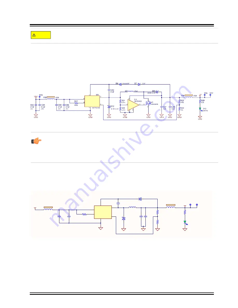
The 12V voltage rail is obtained from the MC16301 buck-boost converter. For a further description about
the buck-boost converter see the
MCP16301 Buck-Boost Converter User's Guide
. If the VDC voltage is
always higher than 12V, it is possible to improve the power efficiency by transforming the converter mode
from buck-boost to buck, see
Figure 3-11. 12V Voltage Design
BOOST
VIN
EN
GND
VFB
SW
VDD
IN
OUT
GND
GND
Restriction:
Note that some power sources, such as USB port and mikroBUS rail, might have
limited current capabilities and they could not supply enough current for the class-D amplifier
transmitting against low impedance values. In this case, an external AC/DC power supply with
enough current rating is recommended to maintain the PLC performance at its best. In case of
using one, we recommend a module complying to national regulations or CISPR 32:2015.
Another buck converter, MC16301, is used to generate a regulated 3.3V voltage rail required by the
PL360 modem and the SAMG55J19 MCU. For a further description about the buck converter see the
MCP16301 Buck Converter User's Guide
.
Figure 3-12. 3.3V Buck Converter Design
3V3
GREEN
D16
GND
600mA max
3.3 Volts
VDC
GND
GND
GND
TP10 TP11
300R
R31
10k
R33
470R
FB6
BOOST
1
GND
2
VFB
3
EN
4
SW
6
VIN
5
U5
MCP16301
GND
1M
R32
4.7uF
50V
C62
4.7uF
50V
C63
0.1uF
C59
B140-13-F
D15
1N4448W
D14
10uF
C60
10uF
C61
15uH
L3
31.6k
R30
3V3 Buck Conver ter
470R
FB7
There are one LED and two test points on each voltage rail to check whether all power supplies are
operating properly.
To avoid on board self-generated disturbances within the PLC signal band, both converters are switching
at 500 kHz fixed frequency, out of the PLC band (95 to 125 kHz).
PL360G55CB-EK
PL360G55CB-EK Board
©
2019 Microchip Technology Inc.
User Guide
DS50002871A-page 24


