background image

MCP39F501 POWER MONITOR

DEMONSTRATION BOARD

USER’S GUIDE

 2014 Microchip Technology Inc.

DS5002240A-page 7

Preface

INTRODUCTION

This chapter contains general information that will be useful to know before using the 
MCP39F501 Power Monitor Demonstration Board. Items discussed in this chapter 
include:

• Document Layout

• Conventions Used in this Guide

• Recommended Reading

• The Microchip Web Site

• Customer Support

• Document Revision History

DOCUMENT LAYOUT

This document describes how to use the MCP39F501 Power Monitor Demonstration 
Board as a demonstration board to evaluate the MCP39F501 device. The manual 
layout is as follows:

Chapter 1. “Product Overview”

 – Provides important information about the 

MCP39F501 Power Monitor Demonstration Board

Chapter 2. “Installation and Operation”


– Provides information on using the 

MCP39F501 Power Monitor Demonstration Board, including 

Section 2.1.3 “Step 

3: Connect the USB cable to a PC with the installed “MCP39F501 Power 
Monitor Utility” software”

 that describes wiring the line and load connections

Chapter 3. “Hardware Description”


– Provides details on the function blocks of 

the power monitor, including the analog front-end design and power supply design

Appendix A. “Schematic and Layouts”

 – Shows the schematic and layout 

diagrams

Appendix B. “Bill of Materials (BOM)”

 – Lists the parts used to build the 

MCP39F501 Power Monitor Demonstration Board

NOTICE TO CUSTOMERS

All documentation becomes dated, and this manual is no exception. Microchip tools and 
documentation are constantly evolving to meet customer needs, so some actual dialogs 
and/or tool descriptions may differ from those in this document. Please refer to our web site 
(www.microchip.com) to obtain the latest documentation available.

Documents are identified with a “DS” number. This number is located on the bottom of each 
page, in front of the page number. The numbering convention for the DS number is 
“DSXXXXXA”, where “XXXXX” is the document number and “A” is the revision level of the 
document.

For the most up-to-date information on development tools, see the MPLAB

®

 IDE online help. 

Select the Help menu, and then Topics to open a list of available online help files.

Summary of Contents for MCP39F501

Page 1: ... 2014 Microchip Technology Inc DS50002240A MCP39F501 Power Monitor Demonstration Board User s Guide ...

Page 2: ... protection feature may be a violation of the Digital Millennium Copyright Act If such acts allow unauthorized access to your software or other copyrighted work you may have a right to sue for relief under that Act Microchip received ISO TS 16949 2009 certification for its worldwide headquarters design and wafer fabrication facilities in Chandler and Tempe Arizona Gresham Oregon and design centers...

Page 3: ... 2014 Microchip Technology Inc DS50002240A page 3 Object of Declaration MCP39F501 Power Monitor Demonstration Board User s Guide ...

Page 4: ...MCP39F501 Power Monitor Demonstration Board User s Guide DS50002240A page 4 2014 Microchip Technology Inc NOTES ...

Page 5: ...e MCP39F501 Power Monitor Demonstration Board Kit Includes 12 Chapter 2 Installation and Operation 2 1 Getting Started 13 Chapter 3 Hardware Description 3 1 Input and Analog Front End 17 3 2 Power Supply Circuit 18 Appendix A Schematic and Layouts A 1 Introduction 19 A 2 Schematics and PCB Layout 19 A 3 Board Schematic 20 A 4 Board Top Silk 21 A 5 Board Top Copper and Silk 22 A 6 Board Top Copper ...

Page 6: ...MCP39F501 Power Monitor Demonstration Board User s Guide DS50002240A page 6 2014 Microchip Technology Inc NOTES ...

Page 7: ...tware that describes wiring the line and load connections Chapter 3 Hardware Description Provides details on the function blocks of the power monitor including the analog front end design and power supply design Appendix A Schematic and Layouts Shows the schematic and layout diagrams Appendix B Bill of Materials BOM Lists the parts used to build the MCP39F501 Power Monitor Demonstration Board NOTI...

Page 8: ...e Save Bold characters A dialog button Click OK A tab Click the Power tab N Rnnnn A number in verilog format where N is the total number of digits R is the radix and n is a digit 4 b0010 2 hF1 Text in angle brackets A key on the keyboard Press Enter F1 Courier New font Plain Courier New Sample source code define START Filenames autoexec bat File paths c mcc18 h Keywords _asm _endasm static Command...

Page 9: ...ces user s guides and hardware support documents latest software releases and archived software General Technical Support Frequently Asked Questions FAQs technical support requests online discussion groups Microchip consultant program member listing Business of Microchip Product selector and ordering guides latest Microchip press releases listing of seminars and events listings of Microchip sales ...

Page 10: ...MCP39F501 Power Monitor Demonstration Board User s Guide DS5002240A page 10 2014 Microchip Technology Inc NOTES ...

Page 11: ...se software is used to calibrate and monitor the system and can be used to create custom calibration setups For some accuracy requirements only a single point calibration may be needed The energy meter software offers an automated step by step calibration process that can be used to quickly calibrate energy meters This demonstration board uses the MCP39F501 Power Monitor Utility software for evalu...

Page 12: ...ip Technology Inc 1 2 WHAT THE MCP39F501 POWER MONITOR DEMONSTRATION BOARD KIT INCLUDES This MCP39F501 Power Monitor Demonstration Board kit includes MCP39F501 Power Monitor Demonstration Board ARD00455 Important Information Sheet Mini USB cable AC Line cable AC Load cable Plastic enclosure ...

Page 13: ... 1 1 Step 1 Wiring connections Figure 2 1 identifies the line and load connections of the MCP39F501 Power Monitor Demonstration Board FIGURE 2 1 Connecting the MCP39F501 Power Monitor Demonstration Board 2 1 2 Step 2 Turn on line load power to the meter power the meter The meter will turn on when the line connection has between 90V to 220V connected 2 1 3 Step 3 Connect the USB cable to a PC with ...

Page 14: ...MCP39F501 Power Monitor Demonstration Board User s Guide DS50002240A page 14 2014 Microchip Technology Inc NOTES ...

Page 15: ...escription FIGURE 3 1 MCP39F501 Power Monitor Demonstration Board Top View Hardware Components Legend 1 MCP39F501 5 Output LEDs for digital I O 2 9V DC Input non isolated 6 Headers for pulse testing isolated 3 Connections to external shunt current sensing resistor 7 USB Connection isolated 4 Configuration jumpers 1 7 6 5 4 3 2 ...

Page 16: ...50002240A page 16 2014 Microchip Technology Inc FIGURE 3 2 MCP39F501 Power Monitor Demonstration Board Bottom View Hardware Components Legend 8 Opto isolators 9 Power supply 10 Current sensing shunt 2 m 11 Isolation IC 12 MCP2200 for USB connection 12 8 11 10 9 ...

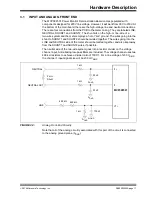
Page 17: ... to SHUNT1 and SHUNT2 should be twisted together The wires going into the LINE and NEUTRAL side of the meter should be twisted together and also kept away from the SHUNT1 and SHUNT2 wires if possible The neutral side of the two wire system goes into a resistor divider on the voltage channel input Anti aliasing low pass filters are included The voltage channel uses two 499 k resistors to achieve a ...

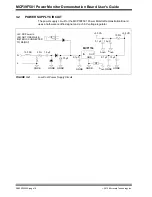
Page 18: ... MCP39F501 Power Monitor Demonstration Board uses a half wave rectified signal and a 3 3V voltage regulator FIGURE 3 4 Low Cost Power Supply Circuit 150 FB 33 1 5 µF 470 µF 1 3 2 N L 0 1 µF 3 3 VD 10 µF IN OUT GND MCP1754 0 1 µF AGND GNDB GNDB GNDB GNDB GNDB GNDB GNDB NT 0 1 µF 10 µF AGND AGND 3 3 VA 100 9V DC Power In DO NOT USE WHILE METER IS CONNECTED TO MAINS ...

Page 19: ...ppendix contains the following schematics and layouts for of the MCP39F501 Power Monitor Demonstration Board Board Schematic Board Top Silk Board Top Copper and Silk Board Top Copper Board Bottom Copper Board Bottom Copper and Silk Board Bottom Silk A 2 SCHEMATICS AND PCB LAYOUT The layer order is shown in Figure A 1 FIGURE A 1 Layer Order Top Layer Bottom Layer ...

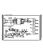
Page 20: ...37 1uF 0603 C25 0 1uF 0603 C24 green red LED RD GN SMD 2 1 4 3 GREEN RED LD1 IL721 3E VDD1 1 OUT1 2 IN2 3 GND1 4 VDD2 8 IN1 7 OUT2 6 GND2 5 U5 MCP2200 VDD 1 OSC1 2 OSC2 3 RST 4 GP7 TxLED 5 GP6 RxLED 6 GP5 7 GP4 8 GP3 9 TX 10 RTS 11 RX 12 CTS 13 GP2 14 GP1 15 GP0 16 VUSB 17 D 18 D 19 VSS 20 U4 0 1uF 0603 C26 MCP2200_RX MCP2200_TX GND_ISO USB_D USB_D GND_ISO 5VUSB USB B Mini TH ID 4 VBUS 1 GND 5 D 2...

Page 21: ...Schematic and Layouts 2014 Microchip Technology Inc DS50002240A page 21 A 4 BOARD TOP SILK ...

Page 22: ...MCP39F501 Power Monitor Demonstration Board User s Guide DS50002240A page 22 2014 Microchip Technology Inc A 5 BOARD TOP COPPER AND SILK ...

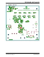
Page 23: ...Schematic and Layouts 2014 Microchip Technology Inc DS50002240A page 23 A 6 BOARD TOP COPPER ...

Page 24: ...MCP39F501 Power Monitor Demonstration Board User s Guide DS50002240A page 24 2014 Microchip Technology Inc A 7 BOARD BOTTOM COPPER ...

Page 25: ...Schematic and Layouts 2014 Microchip Technology Inc DS50002240A page 25 A 8 BOARD BOTTOM COPPER AND SILK ...

Page 26: ...MCP39F501 Power Monitor Demonstration Board User s Guide DS50002240A page 26 2014 Microchip Technology Inc A 9 BOARD BOTTOM SILK ...

Page 27: ... 1 µF 16V 10 X7R 0603 DO NOT POPULATE TDK Corporation C1608X7R1C104K 2 D1 D2 Diode std rec 1A 600V SMA ON Semiconductor MRA4005T3G 1 D3 Diode Zener 15V 1W DO 41 Fairchild Semiconductor 1N4744A 1 J1 Conn power jack male 2 5 mm CLSD CUI Inc PJ 002B 1 J2 Conn recept USB TH vert 5 pos Molex Connector Corporation 500075 1517 1 J3 Conn hdr male 0 100 1x6 pos vert Tyco Electronics 68001 106HLF 5 J4 J5 J9...

Page 28: ...k 1 10W 5 0603 SMD Panasonic ECG ERJ 3GEYJ472V 1 R27 Res 100 1 10W 5 0603 SMD Panasonic ECG ERJ 3GEYJ101V 1 R34 Res 33 5W 1 AXIAL Ohmite Manufacturing 45F33RE 3 R37 R39 Res 390 1 10W 5 0603 SMD Panasonic ECG ERJ 3GEYJ391V 1 R40 Res 1 k 1 10W 5 0603 SMD DO NOT POPULATE Panasonic ECG ERJ 3GEYJ102V 1 R41 Res 10 k 1 10W 5 0603 SMD DO NOT POPULATE Panasonic ECG ERJ 3GEYJ103V 1 SW1 Switch Tact 6 mm 160G...

Page 29: ...Microchip Technology Inc MCP1754ST 3302E MB 1 U4 IC USB TO UART SSOP 20 Microchip Technology Inc MCP2200 I SS 1 U6 MCP39F501 QFN 28 Microchip Technology Inc MCP39F501 E MQ 1 U10 IC Sensor Thermal 2 3V SOT 23 3 Microchip Technology Inc MCP9700T E TT Note 1 The components listed in this Bill of Materials are representative of the PCB assembly The released BOM used in manufacturing uses all RoHS comp...

Page 30: ...ax 86 24 2334 2393 China Shenzhen Tel 86 755 8864 2200 Fax 86 755 8203 1760 China Wuhan Tel 86 27 5980 5300 Fax 86 27 5980 5118 China Xian Tel 86 29 8833 7252 Fax 86 29 8833 7256 China Xiamen Tel 86 592 2388138 Fax 86 592 2388130 China Zhuhai Tel 86 756 3210040 Fax 86 756 3210049 ASIA PACIFIC India Bangalore Tel 91 80 3090 4444 Fax 91 80 3090 4123 India New Delhi Tel 91 11 4160 8631 Fax 91 11 4160...

Page 31: ...Mouser Electronics Authorized Distributor Click to View Pricing Inventory Delivery Lifecycle Information Microchip ARD00455 ...

Reviews: