


2004 Microchip Technology Inc.
DS00908A-page 5
AN908
The computed I
mr
value is then used to compute the
slip frequency, as shown in Equation 2. The slip
frequency is a function of the rotor electrical time
constant, I
q
, I
mr
and the current rotor velocity.
Equation 3 is the final equation of the flux estimator. It
calculates the new flux angle based on the slip
frequency calculated in Equation 2 and the previously
calculated flux angle.
If the slip frequency and stator currents have been
related by Equation 1 and Equation 2, then motor flux
and torque have been specified. Furthermore, these
two equations ensure that the stator currents are prop-
erly oriented to the rotor flux. If proper orientation of the
stator currents and rotor flux is maintained, then flux
and torque can be controlled independently. The I
d
cur-
rent component controls rotor flux and the I
q
current
component controls motor torque. This is the key
principle of indirect vector control.
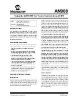
PI Control
Three PI loops are used to control three interactive
variables independently. The rotor speed, rotor flux and
rotor torque are each controlled by a separate PI mod-
ule. The implementation is conventional and includes a
term (Kc*Excess) to limit integral windup, as illustrated
in Figure 6.
FIGURE 6:
PI CONTROL
PID CONTROLLER BACKGROUND
A complete discussion of Proportional Integral
Derivative (PID) controllers is beyond the scope of this
application note, but this section will provide you with
the basics of PID operation.
A PID controller responds to an error signal in a closed
control loop and attempts to adjust the controlled quan-
tity to achieve the desired system response. The con-
trolled parameter can be any measurable system
quantity such as speed, torque, or flux. The benefit of
the PID controller is that it can be adjusted empirically
by adjusting one or more gain values and observing the
change in system response.
A digital PID controller is executed at a periodic
sampling interval. It is assumed that the controller is
executed frequently enough so that the system can be
properly controlled. The error signal is formed by sub-
tracting the desired setting of the parameter to be
controlled from the actual measured value of that
parameter. The sign of the error indicates the direction
of change required by the control input.
The Proportional (P) term of the controller is formed by
multiplying the error signal by a P gain, causing the PID
controller to produce a control response that is a func-
tion of the error magnitude. As the error signal
becomes larger, the P term of the controller becomes
larger to provide more correction.
The effect of the P term tends to reduce the overall
error as time elapses. However, the effect of the P term
reduces as the error approaches zero. In most sys-
tems, the error of the controlled parameter gets very
close to zero but does not converge. The result is a
small remaining steady state error.
The Integral (I) term of the controller is used to elimi-
nate small steady state errors. The I term calculates a
continuous running total of the error signal. Therefore,
a small steady state error accumulates into a large
error value over time. This accumulated error signal is
multiplied by an I gain factor and becomes the I output
term of the PID controller.
The Differential (D) term of the PID controller is used to
enhance the speed of the controller and responds to
the rate of change of the error signal. The D term input
is calculated by subtracting the present error value
from a prior value. This delta error value is multiplied by
a D gain factor that becomes the D output term of the
PID controller. The D term of the controller produces
more control output the faster the system error is
changing.
Not all PID controllers will implement the D or, less
commonly, the I terms. For example, this application
does not use D terms due to the relatively slow
response time of motor speed changes. In this case,
the D term could cause excessive changes in PWM
duty cycle that could affect the operation of the
algorithms and produce over current trips.
K
perr
+ K
i
∫
err
dt
InRef
FB
Out
-
Err = InRef - FB;
U = Sum + Kp*Err;
If (U > Outmax);
Out = Outmax;
else if (U < Outmin)
Out = Outmin;
else
Out = U;
Excess = U - Out;
Sum = Sum + (Ki*Err)-(Kc*Excess);
∑


