


2004 Microchip Technology Inc.
DS00908A-page 3
AN908
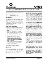
FIGURE 1:
VECTOR CONTROL BLOCK DIAGRAM
Coordinate Transforms
Through a series of coordinate transforms the time
invariant values of torque and flux can be indirectly
determined and controlled with classic PI control loops.
The process starts out by measuring the three phase
motor currents. In practice you can take advantage of
the constraint that in a three-phase system the instan-
taneous sum of the three current values will be zero.
Thus by measuring only two of the three currents you
can know the third. The cost of the hardware is reduced
because only two current sensors are required.
CLARK TRANSFORM
The first transform is to move from a 3-axis, 2-dimen-
sional coordinate system referenced to the stator of the
motor to a 2-axis system also referenced to the stator.
The process is called the Clarke Transform, as
illustrated in Figure 2.
FIGURE 2:
CLARK TRANSFORM
PARK TRANSFORM
At this point you have the stator current Phasor repre-
sented on a 2-axis orthogonal system with the axis
called
α
-
β
. The next step is to transform into another
2-axis system that is rotating with the rotor flux. This
transformation uses the Park Transform, as illustrated
in Figure 3. This 2-axis rotating coordinate system is
called the d-q axis.
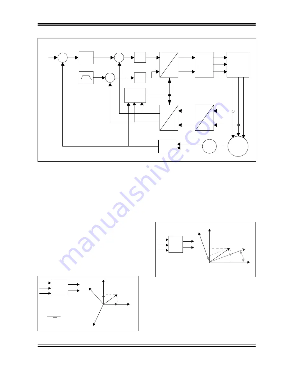
FIGURE 3:
PARK TRANSFORM
From this perspective the components of the current
Phasor in the d-q coordinate system are time invariant.
Under steady state conditions they are DC values.
The stator current component along the d axis is pro-
portional to the flux, and the component along the q
axis is proportional to the rotor torque. Now that you
have these components represented as DC values you
can control them independently with classic PI control
loops.
α,β
α,β
α,β
d,q
d,q
a,b,c
PI
PI
SVM
3-Phase
Bridge
Speed
q
ref
PI
V
q
V
d
v
α
v
β
d
ref
Current
Model
i
a
i
b
Motor
A
B
Speed
Field
Weakening
Encoder
∑
∑
∑
−
−
−
Reference
dsPIC
QEI
dsPIC MC PWM
(Flux
Reference)
(Torque
Reference)
θ
i
a
+ i
b
+ i
c
= 0
i
α
= i
a
i
β
= i
a
+ 2i
b
√
3
α
β
Clarke
a
b
(c)
β
b
a,
α
c
i
α
i
β
i
s
I
q
I
d
Park
i
α
i
β
θ
I
d
= i
α
cos
θ
+ i
β
sin
θ
i
θ
= -i
α
cos
θ
+ i
β
sin
θ
β
q
α
i
α
i
β
i
s
θ
I
q
I
d
d


