background image

7.Attention

Please read the instructions carefully before use

1. Make sure the power supply is stable to get best radar detection
performance.
2. Don’t impact or drop the radar to the groud in case of product damage.
3. The radar antenna is integrated inside. If there is any attachments on
surface of the radar such as water droplets, rain, snow, dust, etc., it should be
cleaned in time.
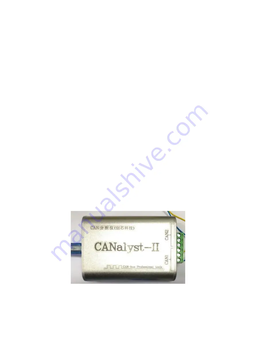
4. the USBCAN box which supports USBCAN(Canalyst-II) and the driver
should be prepared for the radar debug and online testing. The CAN box as
shown in the figure 25 should be used to communicate with the CAR-B51.The
shipping list does not contain USBCAN boxes by default, customers could find
the CAN box link address from Customer Service of Micro Brain Intelligent
Technology Co. Ltd. to purchase the device online.

Figure8 USBCAN box

5. Failed to receive data during testing? Just following the below diagnose

steps:

Check whether the USBCAN box is suitable.

Summary of Contents for CAR-F02

Page 1: ...CAR F02 User manual of CAR F02 Forward Collision Warning Radar 2019 07 30 Microbrain Intelligent Technology Co Ltd...

Page 2: ...sion Warning millimeter wave radar 1 Objects such as vecicles or pedetrians whose range is up to 80 meters could be easily detected by CAR F02 radar 2 The Warning signal could be either CAN communicat...

Page 3: ...s to be connected to the vehicle CAN bus to obtain the vehicle speed When the vehicle speed is greater than the radar starting speed the radar starts to work For the convenience of customer testing th...

Page 4: ...y And the connector should go out to the right Figure 1 Schematic diagram of radar installation direction Installation Location It is recommended to install the radar the downside of the front bumper...

Page 5: ...is and the far away from the radar is the positive velocity while close to the radar is the negative velocity 4 Description Of Interface Cable The CAR F02 radar adopts 6PIN connector The shape and str...

Page 6: ...mmunication protocol Frame ID 0x201 frame type Standard frame Baud rate 500K data protocol 8C AA header V 0xAA 0 1 Unit km h If you send text 8C BE and the starting speed will be set to 19km h 3 Set w...

Page 7: ...shown in figure 4 Figure 4 Upper computer software setting 3 Place the corner reflector at 6 meters 0 3 in front of the radar and the left and right offset is less than 0 2 4 Click measurement button...

Page 8: ...Figure 5 Measuring failure demo Figure6 Measure success demo 5 0m Figure 7 Successful calibration...

Page 9: ...aned in time 4 the USBCAN box which supports USBCAN Canalyst II and the driver should be prepared for the radar debug and online testing The CAN box as shown in the figure 25 should be used to communi...

Page 10: ...Check whether the power supply is connected correctly 12V Check whether the terminal resistance switch of the USBCAN box is on...

Reviews: