Page 14 of 31. Version 1.03 September 2012
Microbee Premium Plus+ | Construction Manual
b)
across IC16 pins 8 & 16 – this should be a fairly large resistance value and represents
the output side of one of the 5volt regulators. Once again, as long as it is not
permanently below 10 ohms, then all is well.
c)
across IC72 pins 7 & 14 – this should be a fairly large resistance value and represents
the output side of the other 5volt regulator. Once again, as long as it is not
permanently below 10 ohms, then all is well.
If you find any shorts in the above steps, check over your soldering work – particularly at
each regulator and correct these before moving on to the next steps.
Power on test
The Microbee Premium Plus runs with an input power supply of 10 – 14 volts DC which is fed
into the main board via the 5 pin DIN connector. 10 Volts is preferred as the regulators will
run cooler.
With the multimeter set to measure D.C. volts and a suitable range selected to measure the
10 – 14 Volts D.C., apply power and quickly measure the input voltage across C71 to
confirm that the power supply is getting to the board o.k.
Measure the two 5 volts rails at:
a)
IC16 – negative meter lead to pin 8, positive to pin 16 – should read +5.0v +/- 10%
b)
IC72 – negative meter lead to pin 7, positive to pin 14 – should read +5.0v +/- 10%
If these are measured o.k. then construction can continue and the un-soldered pins on the 5
key switches can now be soldered.
5. I.C. sockets & PCG ram adapter PCB
Sockets have been supplied in the kit for the larger logic devices including the CPU, PIO,
6545, the Font ROM, the Screen RAMs and the Gold PAL. These can be soldered onto the
PCB now.
There are 3 x 40 pin sockets for locations IC1, IC9 & IC33.
There are 3 x 24 pin (skinny) sockets for locations IC19, 20 & 21. Note that these locations
are actually for 28 pin parts and the 24 pin sockets get soldered into the PCB so that pin 1 of
each socket gets soldered into the pin 3 location on the board – i.e. the left-most 4 pads
(pins 1,2, 27 & 28) are left empty.
There is 1 x 24 pin (skinny) socket for location IC62.
There is 1 x 24 pin (normal width) socket for location IC50.
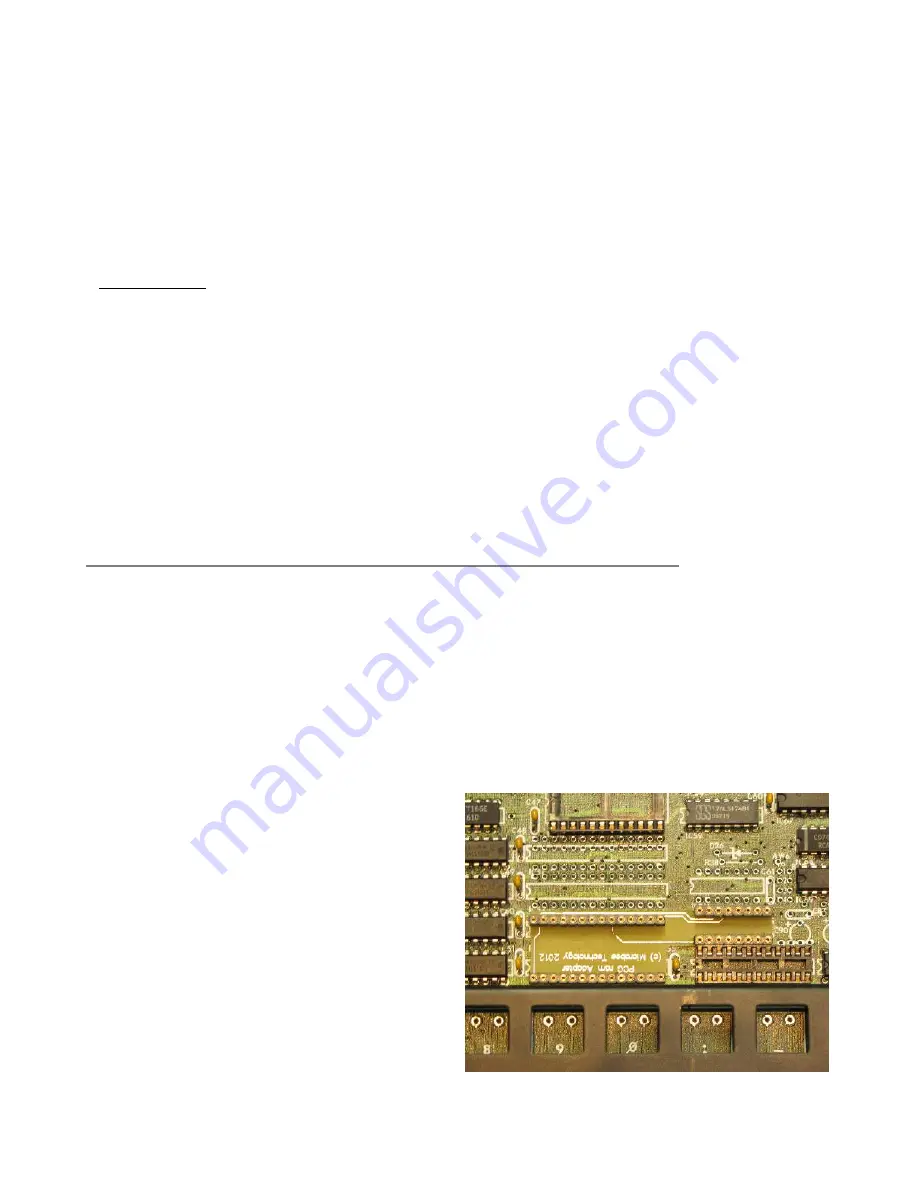
The original Microbee Premium Series
computers were supplied as standard with
16k bytes of Programmable Character
Generator (PCG) memory. The Premium
baseboard was designed for a maximum of
32K bytes of PCG memory however and the
Premium Plus kit includes this as standard.
To implement the full 32k, we have
designed a small adapter PCB that takes a
single 32k x 8 bit static ram rather than the
4 individual 8k x 8 bit static RAMs in the
original design. The adapter is pre-made
and has to be soldered into the baseboard.
The PCG ram adapter board fits onto the
baseboard at IC locations IC53/4 and IC61.


