background image


13.0


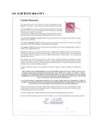
LIMITED WARRANTY 


Summary of Contents for T2000SFL

Page 1: ...Microair Avionics Pty Ltd Airport Drive Bundaberg Queensland 4670 Australia Tel 61 7 41 553048 Fax 61 7 41 553049 e mail support microair com au...

Page 2: ...ate Change 1 0 11 02 01 Initial Draft 1 1 25 05 01 Remote display references removed 2 0 11 07 01 Part Identification Revision 2 1 07 11 01 Deleted SF references 2 2 01 06 02 Pin assignments and wirin...

Page 3: ...4 2 GROUND PLANE 7 5 0 COAXIAL CABLE 8 6 0 WIRING 9 6 1 GENERAL WIRING 9 6 2 AUDIO BEEP 10 6 3 SUPPRESSION IN 10 6 4 SUPPRESSION OUT 10 6 5 EXTERNAL STANDBY 10 6 6 EXTERNAL IDENT 10 7 0 CALIBRATION OF...

Page 4: ...ut IMPORTANT NOTE Installation of this transponder should be carried out or inspected by a qualified installer 1 1 MOUNTING OPTIONS The T2000 Transponder series has a number of mounting options The SF...

Page 5: ...tors M4 MACHINE SCREWS 57MM 2 1 4 INSTRUMENT HOLE NO REAR SUPPORT REQUIRED MICROAIR T2000 SFL PANEL INSTALLATION DB 25 CONNECTOR WIRING HARNESS 50 OHM COAX BNC CONNECTOR The T2000SFL weights only 600g...

Page 6: ...he period can typically be up to 10 minutes The T2000SFL software offers the option of leaving the encoder unpowered until mode C operation is selected This option is useful for operators using batter...

Page 7: ...ntennas 4 2 Ground Plane In metal skin aircraft the skin forms the ground plane To ensure a good electrical connection it may be necessary to remove paint primer from the inside face of the skin befor...

Page 8: ...B m 0 21dB ft 2 0m 7ft 142W 70dBm RG213 A U Mil Spec 125mm 5 0 26dB m 0 08dB ft 5 75m 19ft 142W 70dBm RG223 U Mil Spec 100mm 4 0 47dB m 0 14dB ft 3 2m 10ft 142W 70dBm RG400 Mil Spec 50mm 2 0 60dB m 0...

Page 9: ...all D series plugs via their security screws before operation Aircraft vibration may disconnect a D series plug if it not secured Where possible wiring is to be run separately to the coaxial cable Mi...

Page 10: ...standby mode and stay there regardless of the position of the Selectmode knob The REM STBY function can reverse this operation to make the T2000SFL go to standby when the external standby is not grou...

Page 11: ...er and altimeter in the aircraft This test is typically repeated every two years to ensure the ongoing accuracy of the system Refer to FAA FAR Part 43 appendix E and F for typical transponder encoder...

Page 12: ...IAGRAMS T2000SFL with EC2002 Altitude Encoder T2000SFL with AK 350 Altitude Encoder T2000SFL with A 30 Altitude Encoder T2000SFL with Enigma Multi Function Display T2000SFL with Dynon D10A Multi Funct...

Page 13: ......

Page 14: ......

Page 15: ......

Page 16: ......

Page 17: ......

Page 18: ......

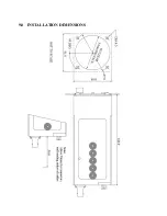
Page 19: ...9 0 INSTALLATION DIMENSIONS...

Page 20: ...TO 20V 9 GILLHAM CODE A1 10 GILLHAM CODE A2 11 GILLHAM CODE A4 12 GILLHAM CODE B1 13 GILLHAM CODE B2 14 SUPPRESSION OUT 5V 15 EXTERNAL STANDBY GROUND TO OPERATE 16 EXTERNAL IDENT GROUND TO OPERATE 17...

Page 21: ...11 0 PANEL TEMPLATE 61 61 57 67 DIA 4 5mm 45 DEG...

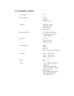
Page 22: ...Hz Pass band Input Power 10 33Vdc 100 150mA 28V 150 200mA 14V Operational Modes Standby Mode 3A Mode 3A C Mode 3A C with Altitude Displayed Dimensions Length 169mm 6 65 Width 61mm 2 40 Height 61mm 2 4...

Page 23: ...13 0 LIMITED WARRANTY...

Reviews: