MICRO-AIR OM550DD Owner'S Manual Download Page 4


OPERATION 

1.  Once all electrical and drain connections have been made 

turn unit on. 

2.  No lubrication is required for the motor because it is a 

permanent pre-lube design. Excessive dirt/oil should be 
removed. 

3.  Make sure oil is draining easily through drain pipe. 

CHANGING FILTERS 

CAUTION: Always make sure that the unit is turned off 
before changing filters or servicing the unit. 

1.  The OM550DD may be equipped with an optional 

Minihelic Gauge, which may be used to indicate when filter 
needs to be replaced. 

2.  Initially, the Minihelic Gauge will register a very small 

pressure drop across the filters (change in pressure varies 
with filter combination used). After continued operation, 
airflow will be reduced and the Minihelic Gauge will 
measure increased pressure. 

 NOTE

: Record pressure reading for future reference. 

3.  Minihelic Gauge will measure increased pressure. 

4.  When the gauge reads high differential pressure, turn the 

unit off and remove the impinger pre-filter form the unit. 
Wash the pre-filter in a detergent solution to remove dirt 
and oil residue.   

5.  Rinse the pre-filter thoroughly with water, shake dry and 

replace it into the with airflow direction pointing to the 
blower.  

6.  Turn on the unit. If gauge continues to read high, 

differential pressure, after replacing the pre-filter, then the 
pleated oil filter may also need to be replaced. 

7.  Visually inspect the pleated oil filter. IF the pockets are 

loaded with oil and dirt, then remove the filter from the unit 
and insert a new filter.  

8.  Start the unit. The gauge should read low differential 

pressure, and the unit operating properly.  

GENERAL MAINTENANCE 

1.  Occasionally check the condition of the door seals for any 

leaks. Replace if necessary. 

2.  Check the blower bearings for unusual wear and the 

blower wheel for debris and dirt. Clean when necessary. 

3.  Check the wiring for loose connections or cracked 

insulation. 

4.  No lubrication is required for the motor because it is a 

permanent pre-lube design. Excessive dirt/oil should be 
periodically removed. 

5.  Make sure that oil is draining easily through drain pipe.  


TROUBLESHOOTING CHART 

CAUTION: Before disassembling the unit or doing any inspection of the parts, make certain that the power has been cut off 
and the blower has come to a complete stop. Never run the unit with the access door open or removed
.


PROBLEM                        POSSIBLE CAUSE                REMEDY 

Unit fails to start                                        Dead power line                                                Check the circuit and switch 
                                                                  Blown fuse                                                        Replace fuse 
                                                                  Loose wire in terminal box                                Reconnect wire 
                                                                  Burned out motor                                              Replace motor 

 
Unit runs slowly                                         Wired for wrong voltage                                   Check input voltage 
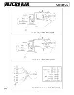
Inadequate capture                                   Improper rotation                                              Check wiring diagram 
                                                                  Dirty filters                                                        Service filters 
                                                                                                                                             (see Changing Filters Section) 
                                                                  Obstruction in hose/arm                                   Reach into hood and remove obstruction 

 
Vibration                                                    Loose mounting bolts                                        Tighten bolts 
                                                                  Foreign objects in blower                                   Remove access door and remove objects 
                                                                  Dirty disposable filters                                        Service filters 
                                                                  Obstructions in hose/arm assembly                   Reach into hood and remove obstruction 

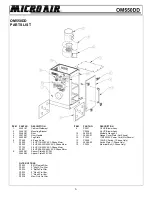
Summary of Contents for OM550DD

Page 1: ...AIR CLEANERS OM55ODD OWNER S MANUAL CAUTION READ COMPLETE INSTRUCTIONS BEFORE OPERATING PLEASE FILE FOR FUTURE REFERENCE ...

Page 2: ...e weight of the unit Three feet of unobstructed exhaust space from the outlet of the unit Easy access to service panels and unit inlet As near as possible to the source of the oil mist unit to be captured 4 Mark location of the mounting holes on the surface to which unit is to be mounted see FIG 2 for hole pattern Drill or punch holes that are sized for mounting hardware to be used FIG 2 5 Lift OM...

Page 3: ...o the nearest outlet rated for 120 volts FIG 4 B THREE PHASE 208 230 460 VOLT 1 Conduit electrical connections should be made by a qualified electrician and must comply with local electrical codes CAUTION Be sure that the designated circuit breaker is off until all wiring has been completed NOTE It is recommended that a motor starter protector be used in the supply circuit to this unit See Wiring ...

Page 4: ...er IF the pockets are loaded with oil and dirt then remove the filter from the unit and insert a new filter 8 Start the unit The gauge should read low differential pressure and the unit operating properly GENERAL MAINTENANCE 1 Occasionally check the condition of the door seals for any leaks Replace if necessary 2 Check the blower bearings for unusual wear and the blower wheel for debris and dirt C...

Page 5: ...5 FIG 5 ...

Page 6: ... Cord Not Shown 6 P3649 4 Prong Knob 13 P3029 120VAC Switch 1 Phase Only 7 P3020 1 2 HP 115 230VAC 1 Phase Motor 14 30386 02 Switch Plate 1 Phase Only P3023 1 2 HP 208 230 460VAC 3 Phase Motor 15 P3025 Electrical Box 1 Phase Only P7122 3 4 HP 115 230VAC 1 Phase Motor P3021 3 4 HP 208 230 460VAC 3 Phase Motor 8 34460 01 Spacer Plate 450 CFM 34460 02 Spacer Plate 550 CFM FILTER OPTIONS P3032 95 Plea...

Page 7: ..._____________________________________________________________________ _____________________________________________________________________ _____________________________________________________________________ _____________________________________________________________________ _____________________________________________________________________ __________________________________________________...

Page 8: ...__________________________________ _____________________________________________________________________ _____________________________________________________________________ _____________________________________________________________________ _____________________________________________________________________ _____________________________________________________________________ _______________...

Reviews: